This is a point that doesn’t seem to get mentioned much re roaming tests and re ABP and OTAA and up and down reception issues, more specifically its one then being able to transmit packets but just as important is the ability to receive them in tests too.
I think…
Basically you can end up focusing all your efforts on node Uplinks via ABP and then when you switch over to OTAA you find Downlinks are having reception issues (ie joins fail)
This is why racing around sending packets every 6 seconds in not showing you the full picture, another approach is to set your node to SF7 on OTAA and have a trigger switch to test joins at a given location - this keeps airtime down, tests worst case re SF7 and tests Downlinks as part of the OTAA connections process.
@jezd, I’m using jumper wires however the length is 10CM including the connector, The 5V & GND are on 20CM Lengths to reach the other side, I’ve also disabled the Wi-Fi & Bluetooth functions of the Pi 3 an am using ethernet.
I am using SF7, From what I’ve read I can increase it but I should be getting at least 1KM before using this.
I’m using ABP as mentioned in my original post, I can increase the time delay however with the fact that such a short distance you’re talking 10 seconds can be the difference of it transmitting a packet or not. The node is just handheld and I’m walking with my dog while walking round the block. I was expecting to drive around with it but obviously with the very poor distance already have no need to drive away to test.
The garage is just a single skin brick, one double glazed door. I can put the antenna outside (which is why I’m looking at possibly buying a better one which is weatherproof however if something else is to blame to begin with I don’t see the point in spending money on something that won’t fix my issue).
@andrewl, Height is about the only thing that I haven’t been able to do anything about as while it could be inside the house I live in it’s only a bungalow so wouldn’t be much higher. (Most of the houses in the complex I live in are also bungalows).
@jezd, If ABP mode sending packets every 6 seconds isn’t showing me a worse case scenario and this is the best case then surely something is even worse as if I can’t even get a good range with settings that should be getting a better range then with settings that use a lower range it’d be worse.
However I really am not an expert. Hence asking on here.
10km range is only when you place the gateway (or at least the antenna) outdoor and on sufficient height (let’s say at least 15m). If you place a gateway indoor, on ground floor you will be lucky if you have a range of a few 100m at all. Jumper wires or not does not have any impact on reception. You should only expect home coverage from indoor gateways.
Like one famous engineer once said: dammit Jim, ye cannae change the laws of physics!
So the solution could be like I mentioned. getting an external antenna. But it could be difficult to put it quite high? How high would it have to be from say Ground level? 15M isn’t likely going to be possible.
I understand that I won’t get 10KM however was expecting at least 1-2KM.
For 10km you need some LOS (Line Of Sight). The signal of node can ‘break free’ out of the building it is in, but it won’t reach an antenna that is inside another building, especially not on ground floor. A rule of thumb would be that the antenna has to be able to ‘see’ all the locations you want reception from. Especially so in urban environments.
Be aware that most Chinese or brand-less antennas don’t have the gain they claim, if they have any gain at all. E.g. one of my setups has the antenna you link to in the first post (albeit a different manufacturer), but it only behaves like a ground plane antenna with no gain. In the best case. You also need quality coax cable and pigtails, especially if you are gonna run several meters between the antenna and the gateway.
Imo it’s better to place the gateway itself outdoors, in a suitable enclosure, and keep the distance to the antenna short.
Moving it outside and about half a meter higher up has increased outside performance slightly but decreased it while inside my house.
I can possibly mount the gateway outside but would only do this if using an antenna that attaches direct to a SMA Connector. Otherwise using the cable to the gateway being inside is more reliable and easier to mount.
With the amazon antenna would the main issue be the antenna or height still? If so would getting a longer antenna also help?
As mentioned before but want to make it clearer. If its under 2KM range then it’s not suitable Ideally I’d be looking for 5-6KM Range as this covers most of the town I live in (which is the point of me buying a proper concentrator board and not continuing using a single channel one for me).
If it matters I’m using the TTN forwarder software , I’m not sure if this is configured weaker than the legacy packet forwarder or not.
Choosing a good antenna is arguably the most difficult task in setting up a gateway. Not because antennas are hard to find, but because reliable information about them is hard to find. But I for one would place all the antennas you link to in the ‘avoid’ category, because these are multi mode wideband antennas, not especially suited for 868MHz. There have been some tests on this forum, and most of these antennas even attenuate the signal in stead of increase the reception.
In selecting an antenna, next to the frequency range you should at least have information about the gain, the radiation pattern and the VSWR. But even then, if this information is not coming from a reputable manufacturer it is to be taken with a grain of salt.
If you want a cheap solution that works pretty well, you can easily make your own antenna. For cheap antennas, some people here (including myself) have ‘good’ experiences with this and this antenna. ‘Good’ as in: it works at least as well as the DIY ground plane antenna.
Like said before, even 2km range will be difficult if the antenna is low and in the vicinity of obstacles higher than itself. To guarantee good reception, you should be able to draw a straight line between the place the node is positioned and the antenna. But you will have to experiment. Start with the DIY ground plane, this antenna has no gain and therefore a wide radiation pattern (no directivity), which you will need in your case. This means that this antenna will be able to pick up signals in almost all vertical directions. Antennas with gain, like the ones you link to or the Aliexpress ones, have a more horizontal radiation pattern and are less sensitive above and below the antenna.
The reason I recommend placing the gateway outside as well is to avoid cable loss. Cheap coaxial cable, like the ones attached to the antennas you link to, can have a loss of up to 1dB/m. If you have a cable like this with a length of 6m, you won’t have much signal left at the other end. The closer you can place the gateway to the antenna, the better. Or buy good cable (e.g. Aircell).
OK, in an attempt to gain more clarity about the “Why” of things, it makes sense to know a bit about what is going on.
868 MHz sits firmly in the UHF band and as such, has certain properties particular to that frequency which are:
UHF frequencies are very much “line of sight” and are attenuated by normal sized (from a human perspective) objects because of their short wavelength (35cm). Think of it like this - if the wavelength is long (e.g. for MW radio - 1MHz), then walls appear 866 times “thinner” to the wavelength. At 866MHz, things like buildings / walls / trees / cars become relatively “thicker” and so they attenutate the radio signal. This is why radio wave transmission between an un-obstructed balloon node and a “in air” gateway can be over many 10s of kilometres, but for a node and gateway in a town at ground level, the range could be less than 300m
There is no getting round it - the best place to site the antenna is up high, with clear “line of sight” and reasonablly away from structures (e.g. roofline) so that impedance matching for the transmitting/receiving electronics is optimal (and so max. power is transferred between antenna and electronics) .
If you live in a high rise block (like many in Europe), the only option may be to site an antenna in the middle of a window of a high rise block. This is because there is no accessable roof to host the antenna in free space (without a long lossy cable) and the wavelength hitting the antenna is smaller than the window apperture with glass obviously being transparent to electromagnetic waves - after all, you can see light through it . However, This is not ideal because of the non-isotropoic nature of the radiation pattern (look it up) because in a similar fashion to when you look out of a window, you can only view things in one direction. The same thing happens with 866MHz radio waves with brick walls in other directions attenuating (dampen) the radio signals, but the effect is not as bad as with light waves where there is 100% attenuation (no-one can see through brick walls)
One good things about this situation is the antenna will be high up, so “line of sight” should be better".
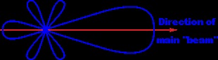
Antennae that offer large dB gain are not amplifying as such, they concentrate the radiation to a contained pattern e.g. The pattern for a Yagi antenna means that away from the directed beam, the signal transmitted and received signal strength is weaker https://en.wikipedia.org/wiki/Isotropic_radiator
There will always be substantial losses resulting from the junctions and cables as follows.
The SMA connector - on the antenna
The U.FL connector - on the PCB)
The cable - U.FL IPX to SMA Female Pigtail
3 antennae that are suitable for gateways are half wave dipoles (which don’t need a ground plane), a quarter wave ground plane or a 5/8 ground plane (identified by a coil incorporated in the antenna ).
If you buy the cheap chinese antenna with a magnetic base. put it on something metallic e.g a metal biscuit tin will do. This will improve performance because the design of the antenna relies on a ground plane being present to be an optimal resonator of radio waves (impedance). This is why the aerial is useful on a car, because the metal skin of the car is used as the ground plane!
From what I can understand I need to look at a better antenna designed purely for 868Mhz (where possible) and if possible have it higher up. The only exception to note is where I live has very little high rise buildings. (They’re less common in UK towns than in cities).
I’ll have a look on Farnell, RS and a few other places and see what options there are.
you’r TTNMapper picture shows no (dark) blue lines, means you are not receiving anything below -115dBm. This could be because of a too high noise level on the input. If you use ~10cm jumper wires between Pi and IMST board that could be the reason.
All these wires behave as antenna, sending noise into the environment. The IMST antenna input circuit and the external antenne itself will pick up these.
Maybe check the discussion on IMST reset problems on the forum.
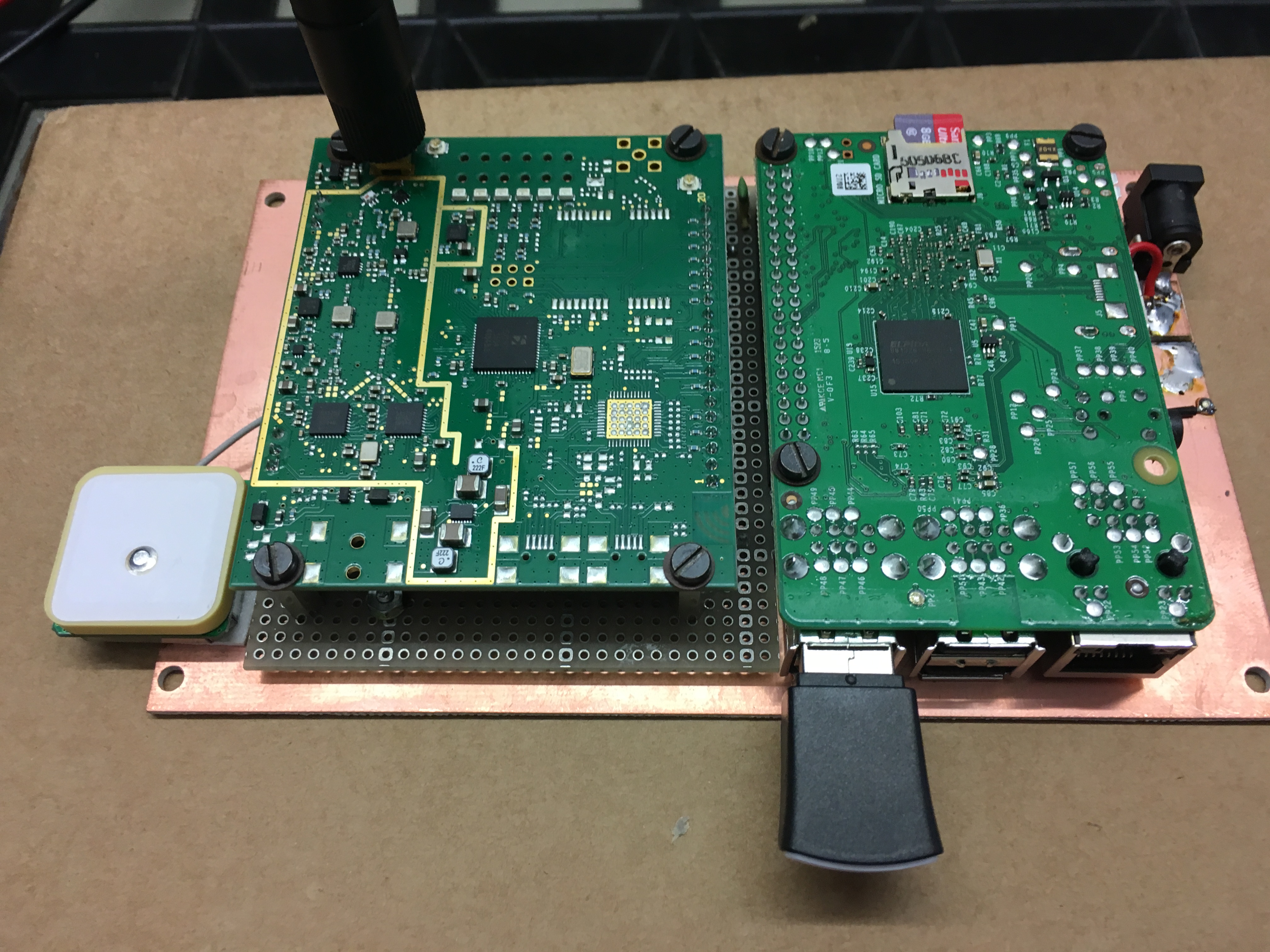
On the picture the setup I’m using already for some years, it works very reliable without any crash or reset ever.
I did experiments with home-made GP antenna and stacked dipole, the last one is some better than the GP but a bit more complex to produce. I recommend the simple homemade GP to start, connect with decent coax cable (as short as possible) to the IMST and keep the antenna away from the Pi and other digital devices.
Wrong way round - Please re-read the responses again.
Choice of Antenna is not as important as placement (height)
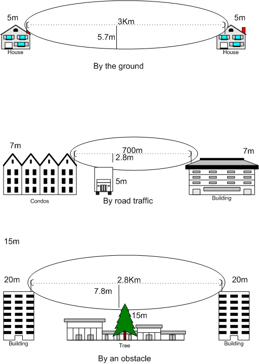
Consider this pic of the Fresnel zone - notice the reduced range of the middle pic
Stop thinking you can buy an antenna to compensate for poor “line of sight” positioning
Its not just being able to see the node, it is also about making sure there is no obstruction which intrudes into the “ellipse”
Move the antenna higher up (think where a TV aerial is - there is good reason why they are there and not where you want them to be ) If the antenna is too close to the ground (which it will be if put on a single story garage), the radiation pattern WILL be severely comprimised and you must expect range to be reduced
I’ll see about either getting a PCB connector made up and try a few different things ( also have some shielding tape I can use). Would high noise level be looking at an improvement in SNR? I can also try some shielding tape I have inside the box.
I’ll look at making the simple GP antenna that you and @epyon linked to, Apart from the base connector I have the other parts required. I can then look at mounting it to a longish piece of PVC Tube. While the cable wouldn’t be as short it’d allow me to get it high up which would hopefully help the most as @CurlyWurly recommended saying height is more important.
One thing about height though could be how high I’m allowed to put it as stuff like this is quite restricted in the UK without permission.
It fits in my price range and I can mount this possibly 50-70CM High from the roof of my garage meaning that it would be ~ 120CM High all in all possibly getting the height aspect solved. I’ll do some more experimenting still with shielding the system for the meantime.
if you keep the long wires it will be hard to reduce the noise, maybe use one of these interconnect boards between IMST and Pi… I’m afraid screening the long wires makes no sense, also the long connection wires not only send signals into the environment they are also sensing glitches, gsm, etc. making the gateway less reliable (unexpected reset ec.)
My antenna is 2 meter above the gateway the connecting coax cable is ~2.5m. Maybe if you copy this construction and use the GP antenna you can do experiments without placing the antenna on a higher position. Just make sure with TTNmapper or the RSSI display in the TTN console you can receive the small signals.
I’ll also be interested in the surge protection methods. I have the RPi Plugged into a surge protector but also a network module I need to connect up too.
While I haven’t done anything yet with the jumper wires I noticed that now the antenna is outside (and I’ve also moved the gateway to another location f the garage where as before it was close by to the power in) while the signal seems worse than I used to get (With the new antenna I got) I now get to a lower RSSI before actually getting no response so it seems height has improved it.
I’ll likely be getting the ~£20 one I linked and mounting it up high and report how it goes .I’ll also see about getting a PCB for the jumper wires instead.
I use a “standard” gateway to calibrate a range of antenna types and sizes. I use the IEEE recommended method for RF testing and calibration that uses a standard dipole closely matched to the frequency. I have an RPi + Coredump backplane + IMST iC880a gateway with the u.fl–SMA pigtail and then a purchased high-quality 1m SMA RG58 coax cable to a Taoglas TI.08.A.0111 antennae purchased in UK from Digikey and positioned vertically. Devices then start in default configuration at a fixed distance of 3m. At this range the TTN core generally reports receiving uplinks with an RSSI of about -22 dBm to -26 dBm. Then I know that all the basics are working correctly and I can start changing one thing - cable, antenna, position, distance, etc. - at a time. The Taoglas antenna datasheets are good as they provide a lot of detail. I would not purchase an antenna that does not provide this kind of detail. LoRaWAN is very low power and so the transmission line, antenna and antenna position are critical. Be aware that LoRaWAN ADR will step in to reduce the device TX power if the gateway RSSI is very strong. DiY antenna work is good for devices but I always use high-quality purchased transmission line and antennae for gateways.
LPWAN coverage range on radio propagation – NB-IoT, Weightless, LoRaWAN & SIGFOX
If you are planning to deploy your own LPWA network then you’ll need to understand a few things about RF signal propagation, run a few models and then conduct a few tests in the real world. In this article, we are going to explore what is involved so fasten your seat belts and let’s go…
First off, remember the maxim, “keep it simple”. We are going to progress through a series of steps and it will quickly become obvious that it makes sense to approach these in sequence.
Step one – Line of sight
It seems obvious, doesn’t it? If you cannot see the location of the end device from the location of the base station then the base station cannot ‘see’ the end device. Buildings that you cannot see with your eyes, because, for example, they are in a valley or behind a mountain, cannot be covered with a base station antenna, at least not reliably, from that height. This is the first stage of any physical network planning process and it is intuitive. The obvious way to maximise coverage is to choose locations where you are able to see a large number of the places where your end devices will be located and this typically means that a base station will be mounted as high as possible. This much is obvious but it makes sense to take this first simple step in your network planning. What is stage two? Modelling…
Step two – Radio Propagation by Excel Sheet
If you have a list of possible base station locations then you can use a radio propagation model to plan the possible coverage from each base station. In the basic step, you use an Excel Sheet and a common radio propagation formula to calculate an estimated coverage range. Each base station antenna coverage will be shown by a circle. The picture as below shows the planning of an LPWAN with six LPWAN base stations at the factory plant of Volkswagen in Wolfsburg.
Read more: http://www.gsm-modem.de/M2M/iot-university/lpwan-coverage-range/
I’ve gone for the antenna that I linked to on eBay and got the cable and connectors today. I’ll be fitting it tomorrow about 21" above my Garage which is the highest I can put it and it’ll also be outside. I’ll report back once I’ve done it and done some testing.
Second update, Not sure if I should have done this as an edit or not but.
New antenna (From eBay) mounted about 1M Above the roof of our garage which is about the same height as our house and the highest I can get it. Gets a range of about 800 Meters, about double the distance but still far far off even 2KM. I have a few more tweaks I need to make (Possibly seeing about wiring the board better between the Pi and IMST Board) and one of the connectors. One thing I notice is while long range is much better short range is worse so I think one of the connectors on it needs replacing.
 . However, This is not ideal because of the non-isotropoic nature of the radiation pattern (look it up) because in a similar fashion to when you look out of a window, you can only view things in one direction. The same thing happens with 866MHz radio waves with brick walls in other directions attenuating (dampen) the radio signals, but the effect is not as bad as with light waves where there is 100% attenuation (no-one can see through brick walls)