With the availability of the CMWX1ZZABZ-078 Arduino core I have started to write application firmware for the various devices with embedded CMWX1ZZABZ-078 modules and test peak and average power usage as well as sleep current.
Grasshopper sleep current is 2.1 uA, LoRaSensorTile 12 uA, and Cricket Asset Tracker 14 uA.
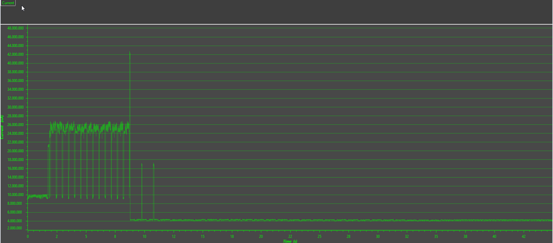
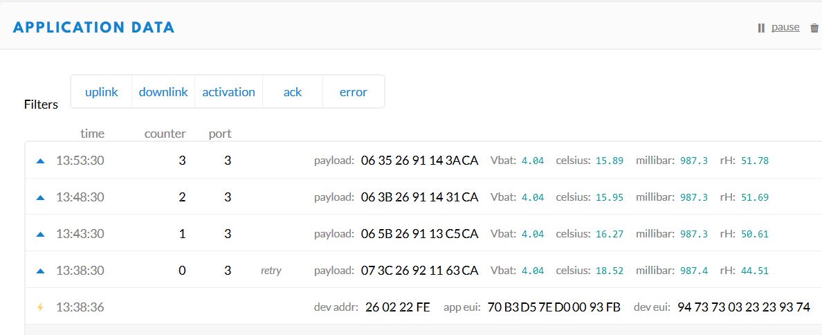
First test of the LoRaSensorTile in use as an edge node casting BME280 and battery voltage data to TTN every five minutes:
shows peak TX power of 33 mA and average power (at 3V3 input) of ~50 uA.
This is with all sensors active (sensor reads once per minute) but the SPI flash is not selected (trying to figure this out now) so I am not actively writing data for logging, but this will affect the average power usage only slightly.
So ~50 uA average power is ~1.2 mAH per day, meaning a LoRaSensorTile edge node powered by a small 3.3 V booster and one AAA battery should last for more than two years.
Good question about future nodes with CMWX1ZZABZ (this is finally a real engineers product name, still cannot type it without getting it wrong the first time).
Kris’s example uses US915, DR_1, TxPowr 10dbm (a reasonable minimum). 7 bytes payload, 13 bytes frame overhead. So that is about 33mA with 177.15ms time on air. That alone is about 19.5uA average (for a 5 minute cycle). Then we got the RX1 window, which is about 2uA. Let’s say RX2 is the same as RX2. So that whole LoRaWAN TX/RX1/RX2 is magnitude wise at 24uA.
So throw in the 12uA sleep/stop current and we are at 36uA. So a real measured ~50uA is anything but shabby, considering that there is BME280 to be dealt with as well …
We’ve started using the grasshopper with a CMWX1ZZABZ-078. We’ve had it working using your sketches, thanks for that. We’re currently working on getting it into sleep mode, yet we measure 1.2mA of current draw when we use STM32L0.stop(5000);. Could you please share the code you’ve done your measurements with? We’re not quite sure wether it’s the STM or the SX inside that’s consuming power. Please help!
I doubt this is a code issue per se. This sketch works and results in a STOP current of 2.1 uA using my multimeter. You have to cut the trace of the power indicator led, since this continuously draws ~200 uA.
What do you have connected to your Grasshopper?
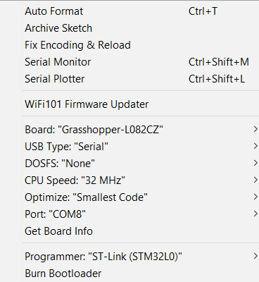
Are you using the Arduino IDE and did you select the Grasshopper board variant?
Not sure how you could get an extra ~1 mA current usage in STOP unless you have the USB connected or something else preventing the MCU from going into stop mode.
@onehorse thanks for the reply!
We’ve removed the LED. The board is completely bare bones and only has the Murata chip on it currently. The only difference being that we upload using a ST-Link: and we debug using Serial1 instead of the usb serial.
We’re measuring the current using a uCurrent: https://www.eevblog.com/projects/ucurrent/ of which I’m quite sure works corrently. Any ideas?
If serial1 is active this might prevent the device from entering STOP mode. You could try serial1.end before entering stop mode and serial1.begin upon exiting.
If this is a custom board then you could have made any number of design mistakes that would prevent achieving lowest power including mishandling the TCXO.
Hi,
Currently i am developing software for my custom CMWX1ZZABZ Murata board.
The software is based on the software provided by ST (STM32CubeExpansion_LRWAN_V1.2.1)
I have designed the board so that i can switch all power domains on or off. I have measured the values of the powerdomains and they seem to be switched when they should be.
When i measured the power consumption of the board i saw that it was way higher then it should be (10 mA between transmissions). I have uncommented: LOW_POWER_DISABLE, DEBUG and SENSOR_ENABLED. In my understanding this should reduce the power consumption of the board and it did with almost 6 mA between transmissions.
I only have the problem that the board still consumes 4mA in the low power mode. This is way more then the ~2uA that it should be in lowpower mode I added the measurements made with energytrace.
additional info:
The sensor that is used consumes ~18mA while in active measurement mode
I have narrowed it down to the void HAL_UART_MspInit(UART_HandleTypeDef *huart) function. Because i have a sensor that is connected to the usart2 i have overwritten the function in the vcom.c file. The power consumption increases from <2uA to ~4mA.
The overwritten function doesnt utilize the DMA functionality of the STM32l0. The questions that i have right now are:
What do the functions do in the vcom.c file?
Could the choice to not use DMA be the reason for the increased power consumption?
edit:
I found a solution to the problem. Since the vcom files are responsible for the PRINTF() i decided to delete the files and change all the functions that rely on the code. By removing the code i managed to get a current of around 1.5uA while sleeping.
Hi!
I hope you all are well; I have a question, could I know the SF I am working on when sending messages?
Depending on the SF the module is in, it should send the information through one port or other thanks.
Yes, that’s true but SF and DR go together isn’t it? Problem is that asking module AT+DR=? always respond value that was pre-configured but not new DR from changing SF because of GW coverage.
That by itself is not a very useful design decision.
What you should think about is that the maximum (legal or at least sensible, depending on where you are) packet length you can send depends on spreading factor.
In terms of how to query the spreading factor / data rate as currently set by ADR from the AT command firmware, that’s not really on topic for a thread about power consumption.
You are right, I opened two or three tabs when looking for Murata topics, and I did not check it was for power usage, entirely my fault. Thanks for your responses.


 and we debug using Serial1 instead of the usb serial.