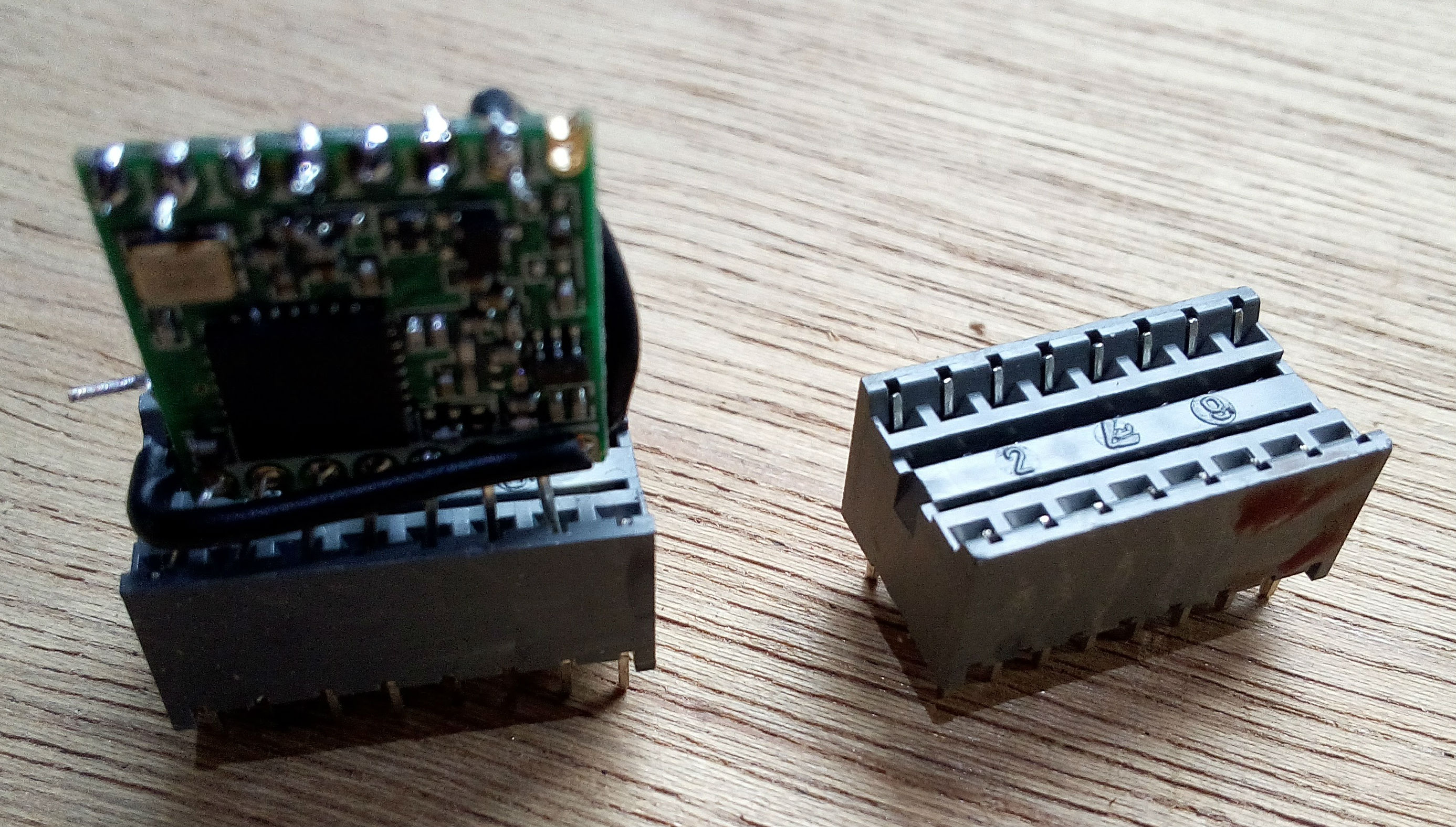
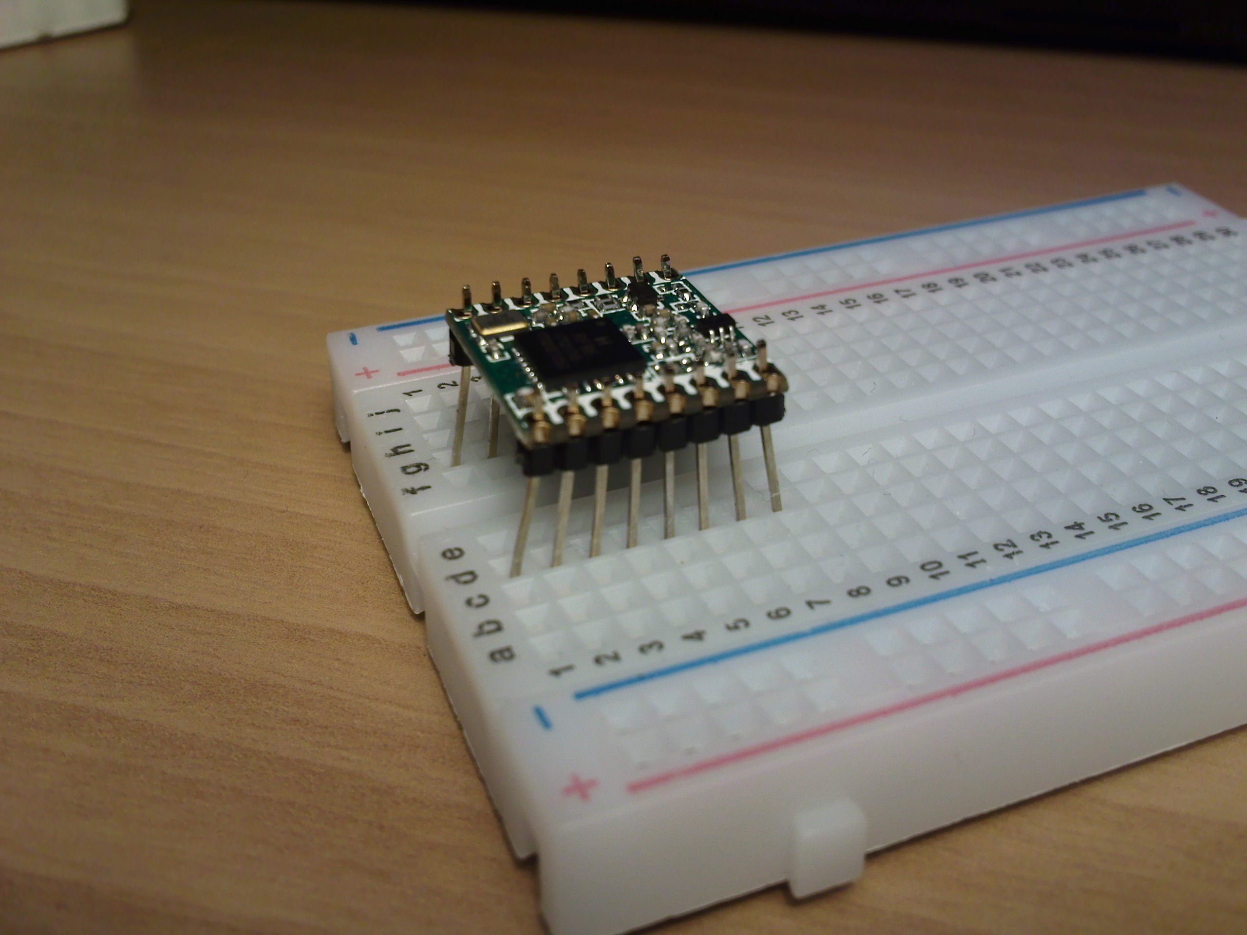
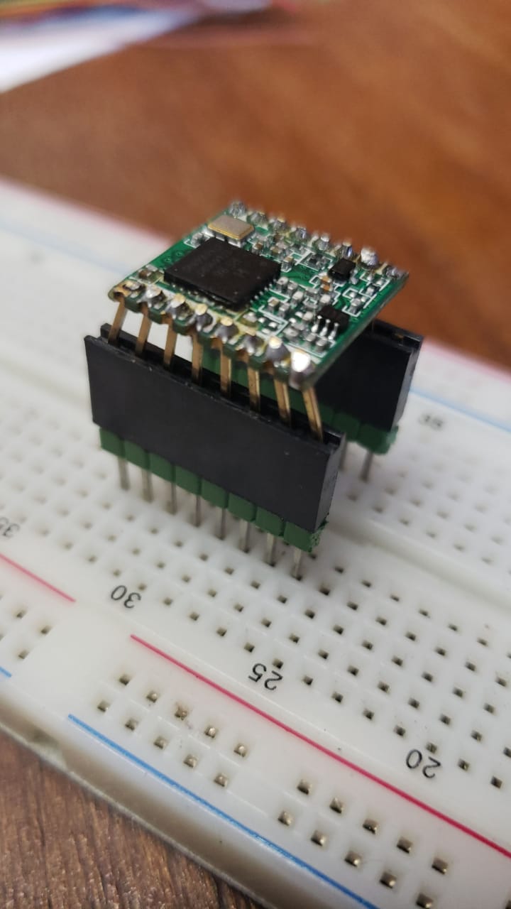
Made a breadboad friendly RFM95 using a 16 pin dil IC socket
2 Likes
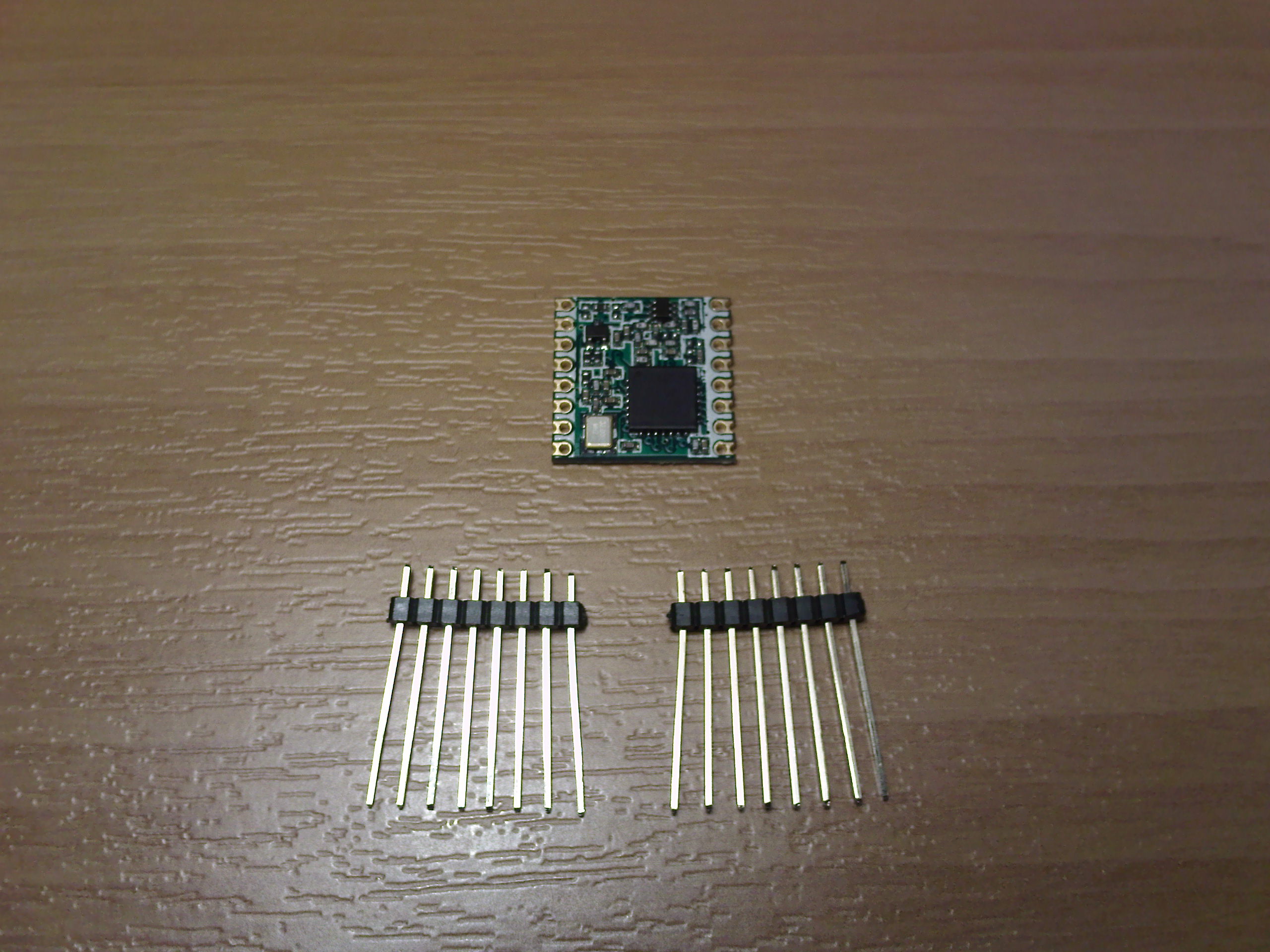
I use 2.0mm headers and 2.0mm to 2.54mm dupont cables
3 Likes
Problem with 2.00 to 2.54 dupontcable is that on the 2.00 side they’re by two and measure 4.29mm so you can’t fit four of them to cover all the 8 pins. But it’s ok if you don’t need all the pins on a given side.
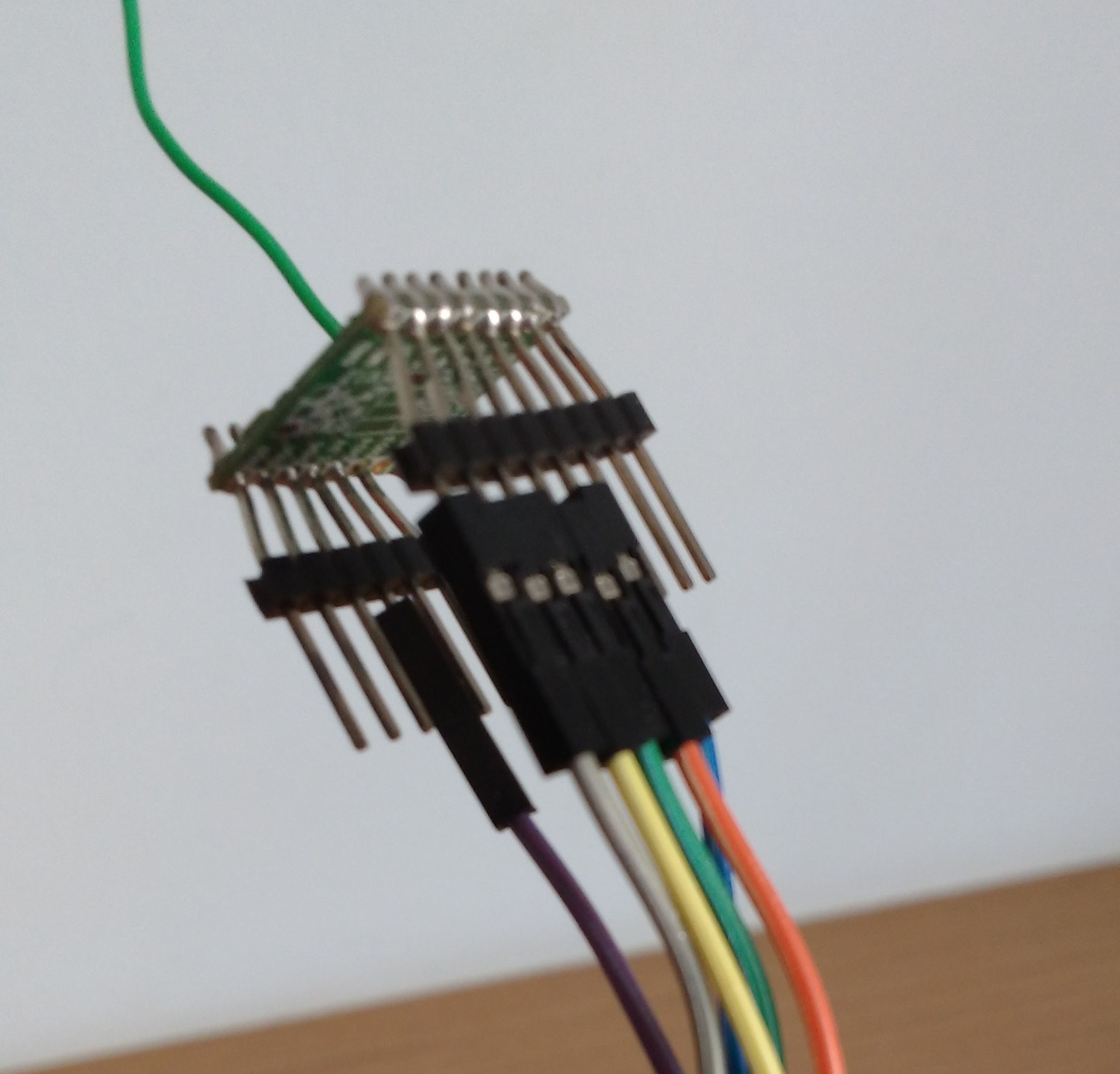
I soldered a 2.54 mm header with long pins bending them with a plier before to adjust to 2.00 mm spaces. The long pins fit well in breadboards and dupont cables.
3 Likes
My solution (soldered 2.0mm male long pins) :
3 Likes
1 Like
Just do it.
4 Likes
Very nice board!! You have eagle files to share?
1 Like
I did not use eagle program to make this PCB. You can order this pcb on Tindie in a few days as 3.5US$ included shipping cost.
2 Likes
They send to Brazil - Rio de Janeiro?
I hope so. Send personal message to me about your address. I will try to send a sample PCB to you.
1 Like
See here for $6.99 breadboard friendly SX1276 (RFM95) module:
Is it free shipping worldwide or only US?
Shipping is from Taiwan so free shipping is probably not restricted to US only.
You can click the link and check it yourself.
Another option for Arduino UNO (and compatibles) is this special dual-pitch prototyping PCB shield:
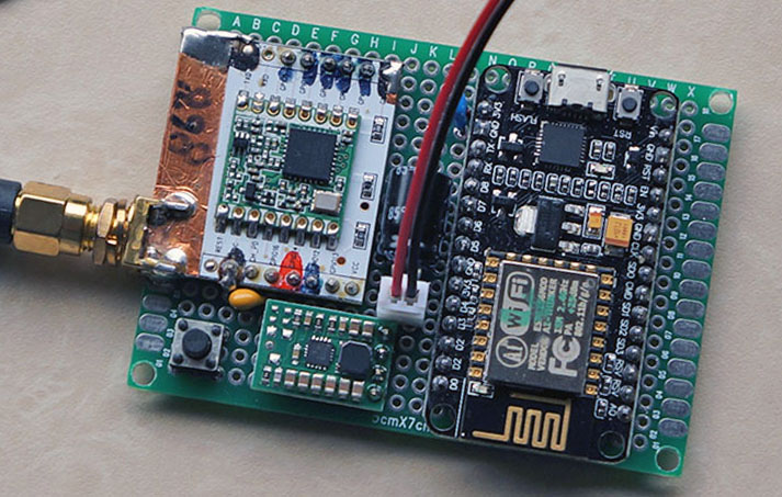
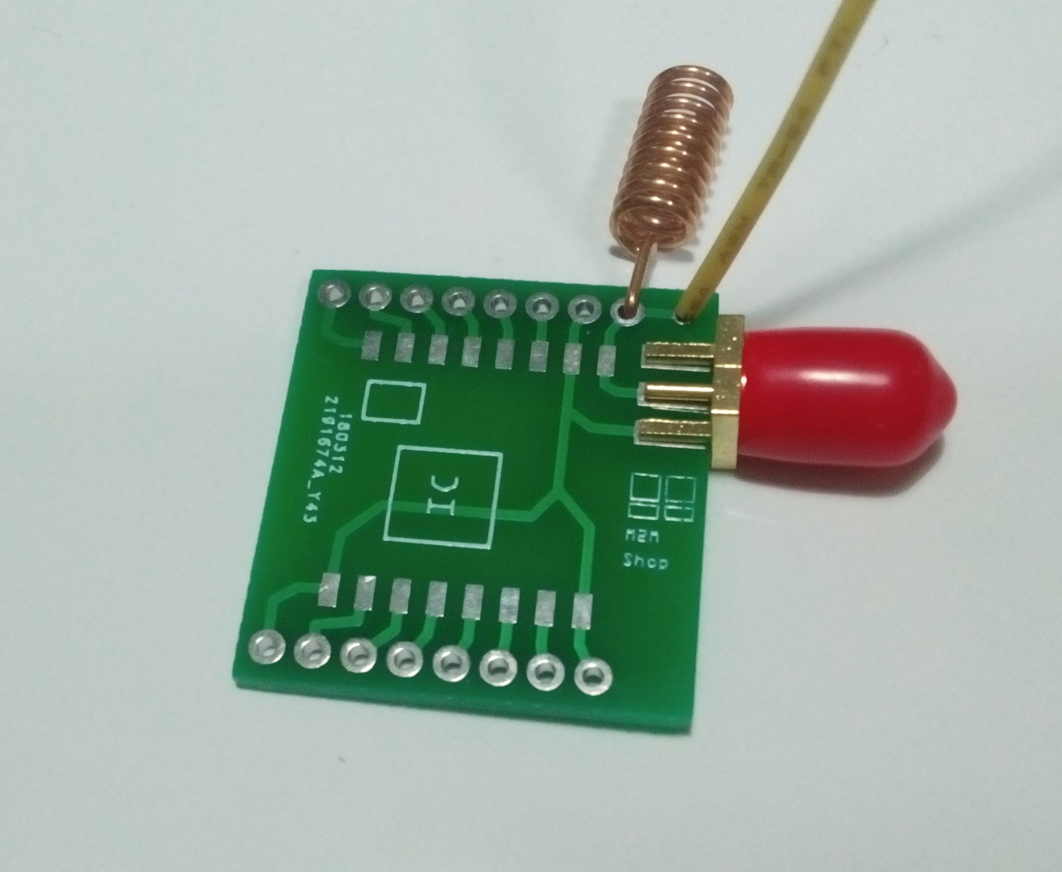
The antenna RF path is critical. Adding multiple paths to the antenna pad like here (SMA, header pin, wire hole) is not good and none of these paths is shielded. Each path will act like a small antenna. This results in impedance mismatch and (possibly major) RF losses.
1 Like
Cutting the tracks leading to unused options close to the mounting pad should help but otherwise agree 