You put pins down to connect easily? That’s what I thought, but I wanted to be as compact as possible …
So that you can easily connect sensors, the pins of the Arduino are a bit above, so you can expand them with your own small perforated boards, or make more PCBs.
One tip:
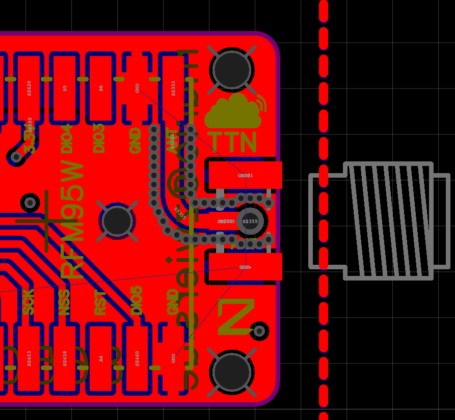
Forme antenna cables around. I have not learned enough ektrotechnik for me to explain, but everybody does it. In addition, I make holes with GND around it, so I get a slight shielding.
And another tip:
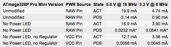
Desolder the LED and the Voltage Regulator from your Arduino. The LED consumes 0.8mA alone! And the regulator 0.05mA.
To the circuit diagram:
I have to be honest and confess that I do not have one. It’s my first own PCB and I did not know about autorouting, so I did everything by hand. The version 2 is completely redesigned and then with schematic!
Love the longboard shape sitting on the back of the battery! Great work…
I’ve been through the rechargeable batteries paths and the self-discharge, especially when temperature varies, is frustrating. I also tried primary non-rechargeable cells, but they’re very, very expensive and need some complicated energy buffering as they cannot deliver more than a 2-5 mA continually (otherwise you cause damage to the cell).
I’ve been experiencing with low-power for while and at the moment having some success with Whisper Nodes and 2xAA. Alkalines are to be cheap and reliable… saying that, I’m really keen to reduce the size of one of my nodes and I’m trying to work with solar harvesting + super-caps (or tiny Li-Po). Found a TI and an ST solar harvesting ICs, just trying it out to see how small can I go with the solar panel. My idea is to transmit every 1h-6h, will post something if I get things to work.
this piece looks like a cool thing. We just wanted to let you know we also crossposted this to our forum because there might be interested people also liking this:
So. My first own blog is ready. I’ve been wanting to do one for a long time and now that I’m spending a lot of time with TTN, I thought it was the best time!
Here is the link to the article about this node. A little more detailed and also with shopping list:
For those who are really interested in my design, I have 10 PCB’s as gift (only shipping costs) in return for your experiences in this forum. The second PCB design planned is a sensor/supercapacitor board (as piggy-back for the Arduino/RFM95). Capacitor charged (in my case) with a 1.5W/5V solar panel.
It looked so good, but it was too good to be true. he has installed the RFM96W and not the RFM95W. on the one hand that means 13 instead of 20 dbi output, but more importantly no lora modulation!
But the solution with the MCP16251 step-up switching regulator is great and I will take on my node. such a board for lora, just for this price would of course top!
Got 2 of these boards graciously sent to me by the Author some month ago for testing.
I wanted to test them but did not had time yet, shame on me, I really need to test them
Maybe you looked at the first link that I posted (of the AVR in stead of LORA node, sorry about changing the link) I think the used LoRa module (Semtech SX1276) is +20dB isn’t it?