Antenna experiment - 868Mhz J-pole

I like to experiment with antennas and at my local Hamradio club (Veron/VRZA Twente) a fellow Ham, who loves the J-pole design, wondered if it was possible to make a j-pole antenna for for 868Mhz. So we calculated the design (with help of this calculator),
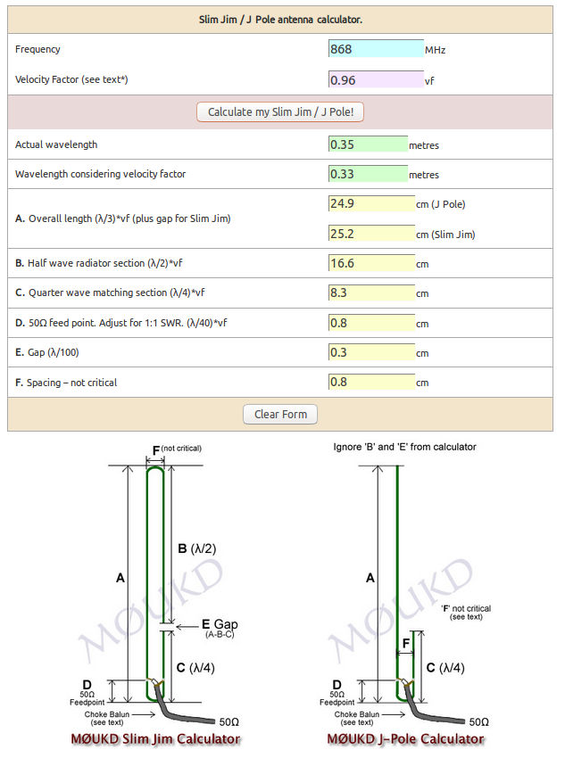
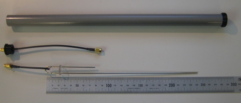
Materials used
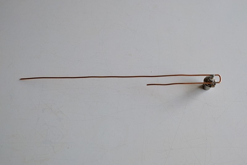
aprx 50cm of 2mm diameter brass or copper wire
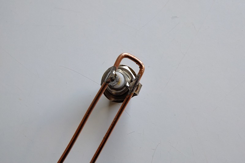
1 x BNC chassis part (no SMA of N was availible in the junk box)

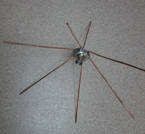
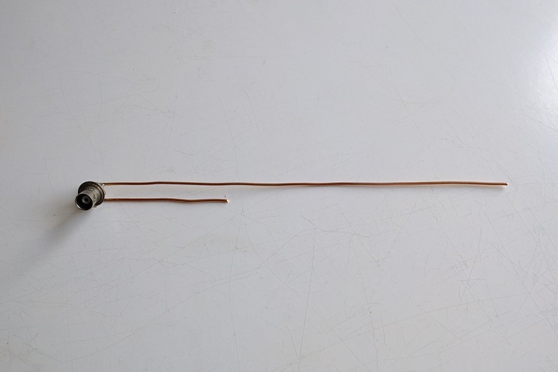
Just a little bending and here are the results :slight_smile:

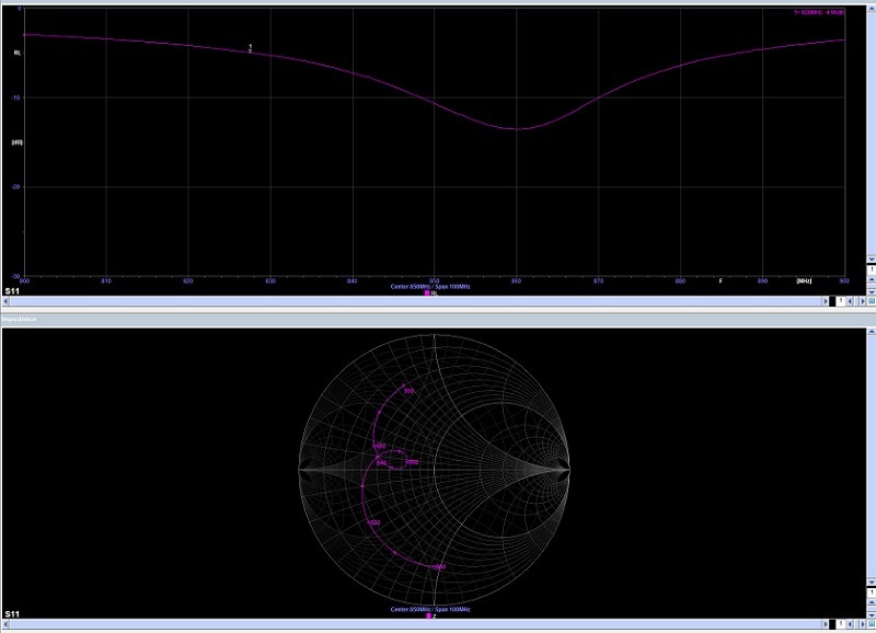
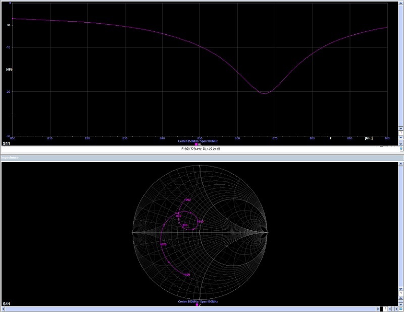
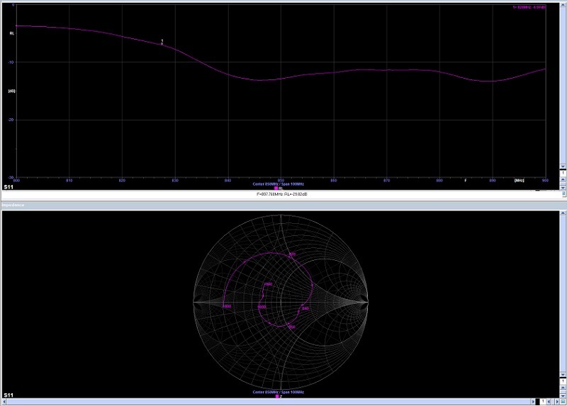
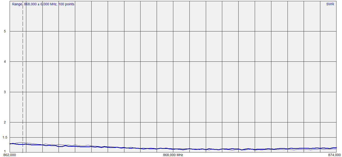
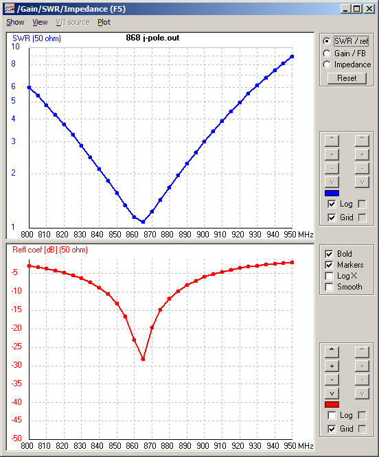
SWR measurment result

After the building we tested it with a RigExpert AA-600 (which when connected to the computer can work up to 1.4Ghz) from the fellow ham and the SWR dip was right on the 868Mhz.

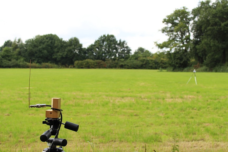
I have tested the antenne in the field and it’s almost as good as the groundplane by default but its a nice antenna experiment :slight_smile:

Simulation

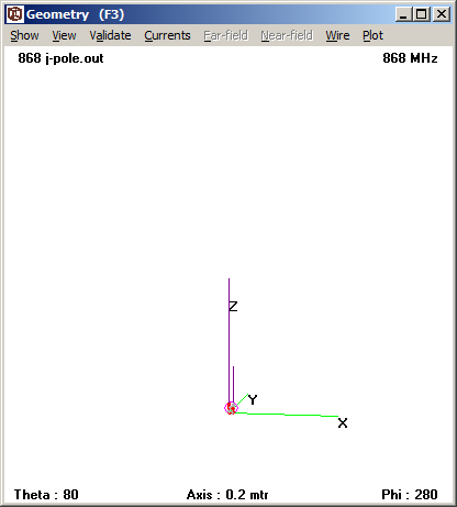
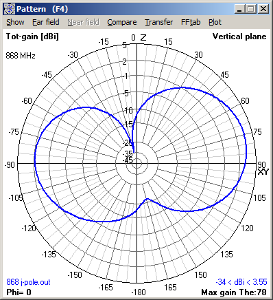
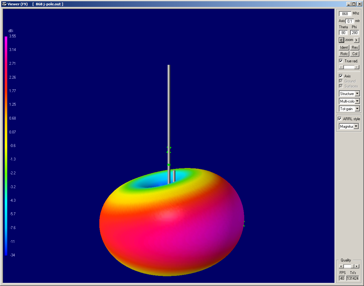
Using the 4NEC2 software I have tried to simulated a 868Mhz J-Pole in freespace and on various heights above good ground.

For these simulations I used the 4NEC2 software which can be download here. Tutorials in 4 parts can be found here : part0, part1, part2. Another good tutorial set is this serie of 4 article publisched in QST : part1, part2, part3, part4 (but off-course you can also google for “NEC antenna tutorial pdf”).

J-Pole in freespace

The NEC file : http://www.ph2lb.nl/blog/forum/images/lora/868_jpole.nec.txt for this simulation.

CM
CE
SY Height=0.25 'Height above ground in m
SY Lambda=0.33
SY Spacing=0.008
SY Feedpoint=0.008
SY Wire=0.002
GW 1 10 spacing 0 height+lambda/4 spacing 0 height+feedpoint Wire
GW 2 5 spacing 0 height+feedpoint spacing 0 height Wire
GW 3 5 spacing 0 height 0 0 height Wire
GW 4 5 0 0 height 0 0 height+feedpoint Wire
GW 5 25 0 0 height+feedpoint 0 0 height+3/4*lambda-feedpoint Wire
GW 6 5 0 0 height+feedpoint spacing 0 height+feedpoint Wire 'Feedpoint
GE 0
GN -1
EK
EX 6 6 3 0 1.000000 0 0
FR 0 10 0 0 868 0.1
RP 0 91 120 1001 0.000 0.000 2.000 3.000 5.000E+03
EN
The NEC file has 5 variables :

Height : variable (in meters)
Lambda : full wave length
Spacing : space between 3/4 and 1/4 lambda wire
Feedpoint : connection point
Wire : wire radius

Now some simulations above realground (average).

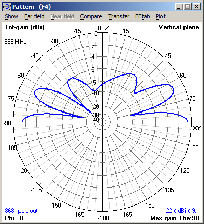
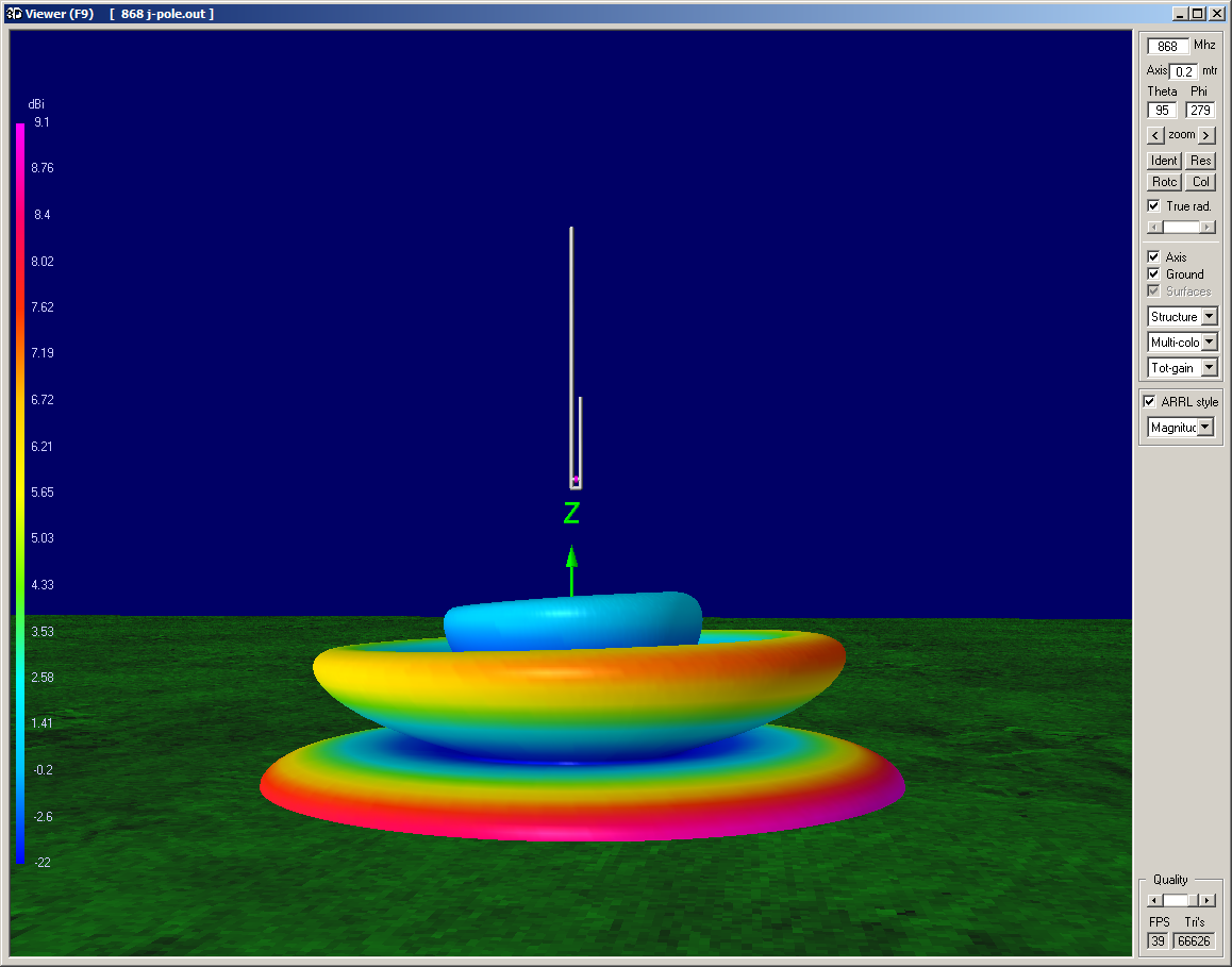
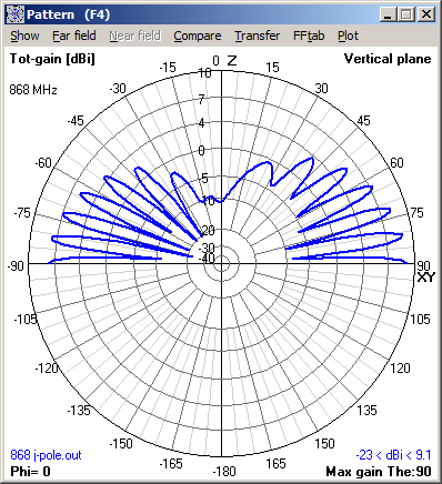
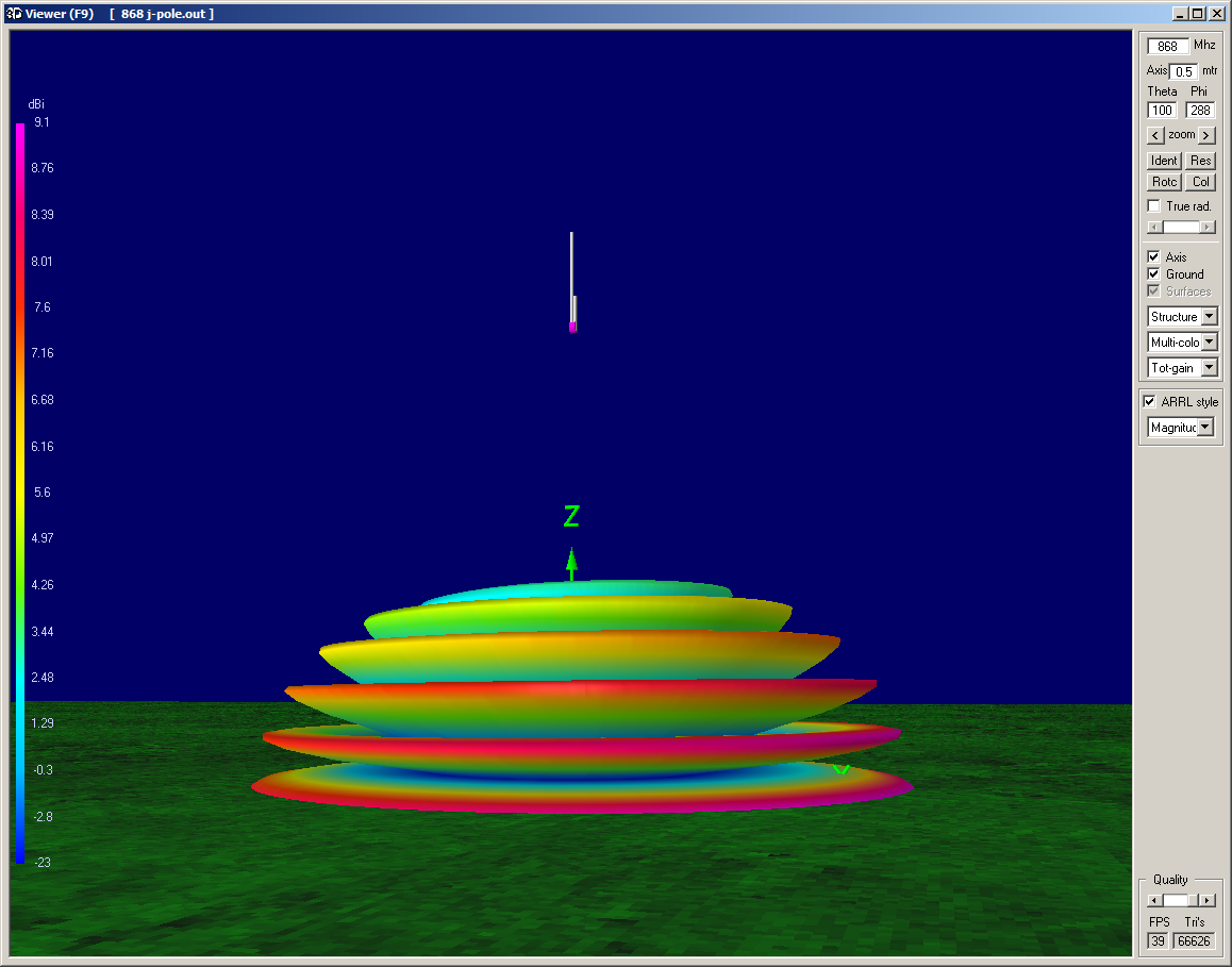
J-Pole 0.25 m above realground

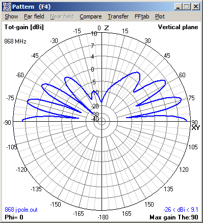
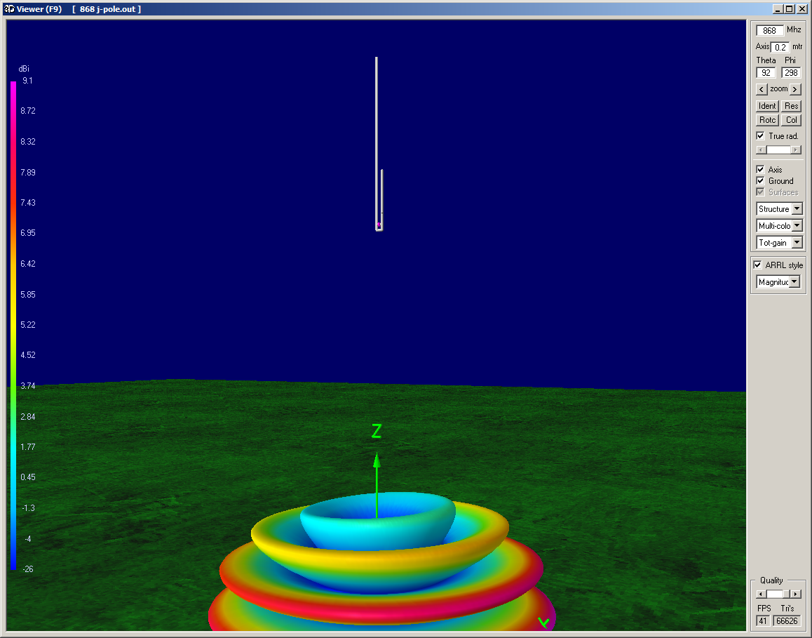
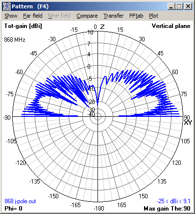
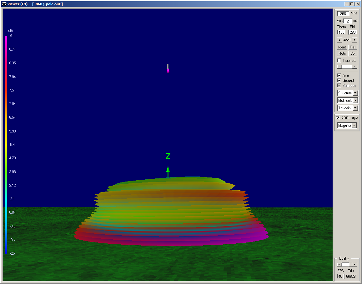
J-Pole 0.5 m above realground

1 Like

Some aditional heights.

J-Pole 1 m above realground

J-Pole 5 m above realground

2 Likes

nice experiments !

would a ‘Cloverleaf’ antenna be possible too ?

can you provide some insight in antenna polarisation and whats best for lora communication ?

You have read my mind, because that would be the next antenna which I’m building. I already made one for 1250Mhz hamradio ATV and the concept works.

Regarding you antenna polarization question, that exactly the reason i want to build one. The most nodes will probably use a vertical antenna, but maybe there are also nodes with a horizontal antenna (tip over node, simple horizontal dipole, helix, etc). This antenna is having both horizontal and vertical polarization (because of the circular polarization) so in respect to a -3dB loss it it can handle both. But knowing that the difference between horizontal and vertical polarization is -20dB (for example horz node, vert gw = -20dB), the large dynamic range of LORA can handle that for nearby nodes to receive.

Based on my experience in hamradio, I would say most nodes will use vertical polarization. In hamradio vertical polarization is used for non directional communication where horizontal communication is mostly used for directional communication. But also there is a practical part in that :

Quote : "Polarization — the orientation with respect to the ground of the antenna and the radio waves from it — is most important on the VHF and UHF bands, where signals usually arrive with their polarization largely intact. If the radio wave and the antenna are oriented differently, the antenna won’t receive the radio wave very effectively.

FM operating is done with vertically polarized antennas because vertical antennas on vehicles are much simpler to construct and install. Vertical antennas are also omnidirectional, meaning that they transmit and receive equally well in all directions. These characteristics are important for mobile operation — the first widespread use of FM. To prevent cross-polarization, the base antennas are vertical. This convention is universal.

A popular and inexpensive vertical antenna is the simple quarter-wave whip, or ground-plane, antenna. Many hams build a short ground-plane antenna as a first antenna project.

Operators chasing long-distance VHF and UHF contacts use beam antennas that are horizontally polarized. Many of the long-distance VHF and UHF propagation mechanisms respond best to horizontally polarized waves. If you have an all-mode radio and want to use it for both FM and SSB/CW/digital operating, you’ll need both vertically and horizontally polarized antennas."

Source : http://www.dummies.com/programming/ham-radio/basics-of-very-high-frequency-and-ultra-high-frequency-antennas-for-ham-radio/

When you’re interested, the free PDF of the book “Hamradio for dummies”, can be download on this link). Recommended reading for every one who wants to get into wireless communication (I have the paper version on my bookshelf :blush:).

1 Like

Hi Lex,

did you do any tuning on the feed point?
The feed point determines the actual impendance of the antenna and as such determines the VSWR ratio measured.
Don’t forget to add a choke around the antenna cable to prevent the cable from radiating and being part of the antenna.
Having the antenna cable running horizontal away from the antenna will influence the antenna and the radiation pattern.

The VSWR ratio seems good, but remember that VSWR is not that important. For larger powers this is important since reflected power will affect the end-stage of the transmitter but the output of the LoRa node is just +14dBm (25 mW) so even a 1::2 VSQR ratio will result in just 2.5mW reflected power - something the chip can easily handle.
More important is the radiated power from the antenna. A 50 ohm termination has a perfect VSWR but as you know it will not radiate any power ;).
Also take into account the cable. RG58 has a 15 dB/100m dampening so a 1::2 VSWR ratio will have the same effect on the radiated power as 3.3m of RG58 cable :open_mouth:

Nice to hear that radioamateurs are also present on this TTN platform.
After all, lora is a digital wireless modulation technique that remembers me of the layer 2 AX25 protocol used on the APRS platform, be it on 2 m (144.800 Mhz).

I love to see more contributions on antennas as the coverage of low power signals is important in this respect.
73s de on3zoe,
Wim.

1 Like

We have fiddled a little around with the feed point to get it close to the 50ohm match. but shifting and soldering 0.1mm steps is a bit hard :blush: . But you are absolute right on the mounting of the horizontal cable. Normally I would use a small piece of semi-rigged coax cable, but for this “see if it works” project we used what was in the junk box (the BNC chassis part). A week later we made another one for 23cm and we did use the Semi-rigged for that (because the soldering points needed to be very small).

I do have a few of those perfect match - broadband - radiation less antenna’s. The work perfect . . . for testing. But a VSWR 1:2 = 10% loss of power (the horror we do have so little) :scream:

Regarding the RG58CU . . . using that on LORA frequencies . . . I would call it natural selection. Because at 100m it will have a attenuation of aprx. 45dB. The normal RG58 has even 70dB.

Source : http://www.coaxshop.nl/rg-58-cu-coax-kabels.html

Thats one of the reasons I like to work with the Aircell 7, I could use the HyperFlex or EcoFlex cables but working with 10mm+ diameter cables is like plumbing. (but sometimes you just need it). LOL
That’s why a wrote a step about cables in this LAB https://www.thethingsnetwork.org/labs/story/simple-homemade-outdoor-868mhz-antenna-groundplane/step/step-6-cable (the RG-58 note in that step is for the normal non CU RG-58 cable).

Nice to meet you on this medium OM Wim, I would have expected more radioamateurs but I think it’s not that well know in the hamradio world (ISM frequencies doesn’t have a top prio there). Having experimented with LoRa for a while (just wanted to know what it is and you can do with it), one evening at the Veron/VRZA Twente measurement group it came up and ended in a good discussion about the technology and possibilities. The week after that one of the OM’s told me he ordered a few RFM95W to start experiment with it (don’t know if he will be joining TTN but time will tell).

In the Twente area of the Netherlands there now are a few hamradio operators giving support to TTN experiments and actively participate but I can’t speak for the rest of the Netherlands.

Personally I haven’t done much with 2m AX25 except for (had) having a receiver / modem on my server to pickup any APRS messages. But I believe that packet radio is, except for APRS, close to QRT in PA.

Just a idea : maybe it would be nice to start a topic on the forum where hamradio operators can announce / introduce them self and offer support for there local community when there are RF related questions / problems.

73 de Lex PH2LB

Indeed - I mis-read my own table. 54 dB/100m means that in my previous example 1m gives the same power loss as a 1::2 VSWR match.

I used to be a radio amateur but work is now giving me enough challenges to play with but the amateur in me is popping up again and now I’m making (and testing) all kinds of antennas using our network analyzer :slight_smile:

Once a ham, always in the blood.

Some OM’s go QRT for more then 10 years but due to new technologies, change in licenses and/or new opportunities (think about PSK and other digital modes), often it start to itch and they are calling CQ again :slight_smile:

Hope to meet you on the bands again.

1 Like

The same on this end Lex,

we went QRT more then two decades ago, but when we discovered by accident the new digital technologies we started ‘CQ-ing’ again, not by voice but by ‘bit and bytes’ (mostly SDR technology and no vintage gear).
Just as you are involved in IT (QRZ --> PH2LB), we are too in system engineering and telecommunications education.
So nice to meet you on the new airwaves here and we are following this thread to see if other ham enthusiasts are presenting themselves with new ideas on use cases or antenne constructions for a loraWAN infrastructure.

73s de on3zoe,
Wim.

After a busy weekend I finally did some antenna measurements.

The J-pole was always one of my favorites. As a student I had not much money to spend on my equipment and not much room to place an antenna so I built a J-pole for 2m to be able to reach our local repeater with my old handheld tranceiver. So when I started my LoRa developments, the J-pole immediately came up as a nice antenna. It’s small, easy to build and does not take much space (read: does not attract too much attention when mounted outdoors).

The antenna works, that’s for sure, but how easy is it to make one in a reproducible way without the need of expensive equipment to tune the antenna.

This is what I built:

It’s a 2mm welding wire, bent around an 8mm drill bit to get the right curve. Three round polycarbonate discs keep it centered in a 16mm plastic tube and a standard SMA cable was cut and soldered to the antenna feed point.

The Antenna is 24.9mm long, the short part 8.3cm and the feed point is at 8mm from the bottom. This gives the following diagram on the network analyzer:

It is not that visible due to small numbers, but the dip is at 860 MHz and had a 13dB return loss. The bottom diagram shows the impedance: The horizontal center line is a pure reactive impedance so the antenna acts almost as a pure resistor (which is good).

Moving the feed point to 9mm shifts the frequency at which the return loss is optimal towards 865 MHz but the impedance stays almost the same (only around a different center frequency)

These measurements were made with the plain antenna, not mounted in the PVC tube. Placing the antenna inside the tube results in a drop of the frequency of the antenna. This is due to the influence of the plastic around the antenna on the velocity factor. After recalculation I end up with a velocity factor of 0.93 resulting in 24.1 and 8.0 cm for the legs of the antenna.
I tuned the feed point (with the PVC pipe attached) and ended up with the feed point at 10mm. Moving the feed points a little bit does not change the behavior of the antenna that much. It stays somewhere between 15 and 21dB but 10mm seems optimal:

As a comparison I did some measurements on the “John Deer” antenna that’s being sold by a number of shops:

This is a dual band 868/915 antenna with 9dBi gain. The return loss is (at 13dB) a bit worse than with the J-pole but still not that bad. With a 5% power return loss instead of 1% is still good. With the small powers of a LoRa tranceiver it still won’t damage your equipment.

So I’m happy with the results. The antenna length is not that critical (+/- 1mm does not change the antenna that much) and placing the feed point at the right place is easy.

8 Likes

Nice story with good info Rob. Thanks for sharing.

Hi Rob,

Looks great, definitely one to try out :+1:. You posed a question:

How would you rate that? You used an analyzer that is able to produce quite fancy pictures, so probably it isn’t cheap? :blush:

Do you think we can get decent results with just the layout you described without using an analyzer?
I guess your PVC pipe passed the microwave test? (although 2450 Mhz is not 868 Mhz ;-)).

Expected gain is typically 2.2 DBi in the H(orizontal)-plane I understand? (assuming you put the antenna upright).

How about our 434 and 915 Mhz friends, I guess its just scaling the math?

How would you rate that? You used an analyzer that is able to produce quite fancy pictures, so probably it isn’t cheap?

Depends on what you call cheap.Compared to Rohde & Schwarz analyzers the Megiq VNA is cheap but for most of us around 4k EUR is a lot of money :wink:

I made way more measurements that the few posted. I played around with the feed point and the length of the legs of the antenna to see how much this influences the frequency and return loss. Looking at the fact that it was not that hard to tune the length and the position of the feed point within 1mm, I concluded that it is not that hard to create more antennas with equal performance.

I actually made the original antenna using the same calculator and number provided by Lex and that one was almost spot on. After placing the antenna in the PVC tube I calculated the new valocity factor and the new antenna was (again) spot on but could be improved by placing the feed point 1mm further.

I wrote something similar in my previous post but that got lost when WIndows 10 had the excellent idea of rebooting my PC before I could press the reply button :dizzy_face:

The next thing to do is to bend a few more welding rods and test then on the analyzer. The analyzer is something I can borrow from the office but it’s being used right now by another colleague to test a product we sell so I don’t expect any new results before end of next week.

Hi everyone,

On Saturday the 5th of November we are organising a LoRa hackfest at the SODAQ HQ to exchange ideas, thoughts, designs etc. on LoRa antenna’s and boards. You guys want to come?
We have some prizes for the best antenna design to be won!

Hello JanWillem,

I would have come, but that Saturday I’m all ready participate in the home brew exhibition at the “Dag Voor De Radioamateur” ( https://www.veron.nl/evenementen/dag-voor-de-radio-amateur-dvdra/ ) showing and demonstrating some of my home brew projects.

868 mhz flarm GP - http://www.bytebang.at/Blog/Building+a+cheap+FLARM+basestation+antenna#

FLARM wikipedia info
FLARM diy info

FLARM is an light aircraft early warning system on 868 Mhz ! :open_mouth:

2 Likes

Hi everyone,

I use such a J-pole antenna (left over from an older FLARM project) for my single channel gateway and did some range experiments with ttnmapper.

http://ttnmapper.org/experiments/map.php?name=DrTestRies_201703191619

Gateway: RasPi + RFM95 + J-Pole located indoors on my window board
Mobile station: homebrew 5/8 wavelength antenna with magnet-mount on my car + node with RFM95 module.

My antenna is made of 1.3mm solid copper wire:
251 mm (long leg)
83 mm (short leg)
7 mm spacing
feedpoint 9mm from bottom
no radome/pipe

2 Likes