Hi
please have a look,
<a class=“attachment” href="/forum/uploads/default/original/3X/9/7
/97f10dc72ab3b0bca893a1486387807c10859085.txt">radio.txt (30.4 KB)
jpy
Hi
please have a look,
<a class=“attachment” href="/forum/uploads/default/original/3X/9/7
/97f10dc72ab3b0bca893a1486387807c10859085.txt">radio.txt (30.4 KB)
jpy
from memory this is a board manager mismatch issue, what dev platform are you using and what board config are you using too?
This has already been asked above. Let’s wait for a response on that first.
Based on the failure message the dev platform is presumably Arduino IDE
Arduino IDE
Esp32 dev module
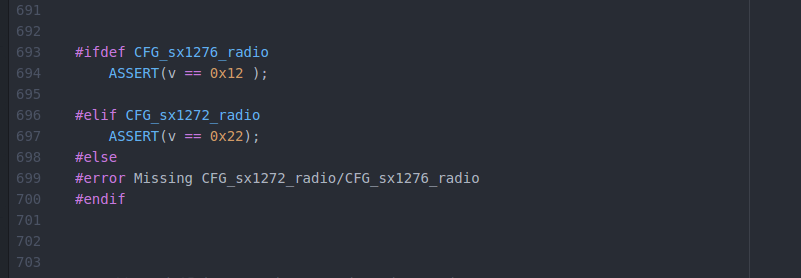
It’s most likely an incorrect configuration of the SPI bus. The assert verifies the result of the first SPI operation (reading the version number from the chip).
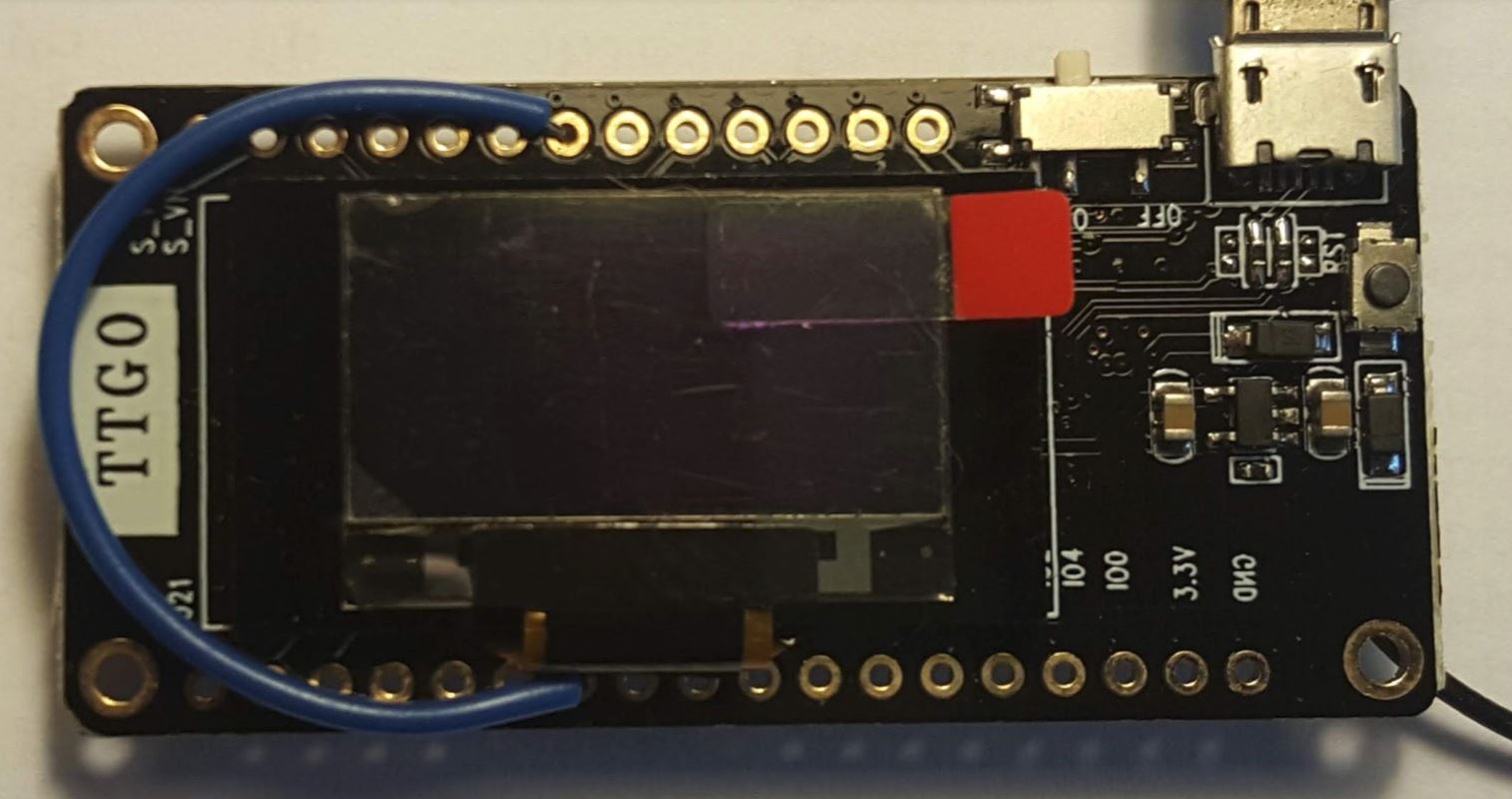
Check if you are using the correct pin numbers. If I’m not mistaken, the TTGO boards all use the following pins:
SCLK  5
MOSI  27
MISO  19
NSS   18
In particular, check NSS.
this is the pin config I used
//For Heltec Wifi LoRa 32, TTGO LoRa and TTGO LoRa32 V1 use:
const lmic_pinmap lmic_pins = {
.nss = 18,
.rxtx = LMIC_UNUSED_PIN,
.rst = 14,
.dio = {/dio0/ 26, /dio1/ 33, /dio2/ 32}
};
Board TTGO Lora V1 915mHz
IDE Arduino 1.8.5
Board:- ESP32 Dev Module
arduino AVR boards 1.6.23
No Hardwiring. Trying with base ckt.
I tried with no of basic LoRa programs and it worked fine as the sender and receiver I could transmit signals from one board(sender) and received on another (receiver) one.
Pin mapping used :-
//For Heltec Wifi LoRa 32, TTGO LoRa and TTGO LoRa32 V1 use:
const lmic_pinmap lmic_pins = {
.nss = 18,
.rxtx = LMIC_UNUSED_PIN,
.rst = 14,
.dio = {/dio0/ 26, /dio1/ 33, /dio2/ 32}
};

joby
Some of the other SPI pins is probably incorrect.
Either select some “TTGO LoRa32…” board in Arduino or go to hal_spi_init() (in hal.cpp) and explicity set the pins:
SPI.begin(5,19,27);
From the Topic Start:
You have selected a different (read wrong) board than the one suggested in the Topic Start. Therefore the SPI pin definitions (defined in ESP32 Arduino Core and can differ per board) are incorrect.
In Boards Manager select the board that is suggested in the Topic Start.
Do you mean TTGO LoRa or TTGO LoRa32 V1?
Both TTGO LoRa and TTGO LoRa32 V1 should have the DIO0, DIO1 and DIO2 pins wired on board by default, so in that case no manual wiring is required.
Hi
I am sending my previously mentioned “sender” code (sender .txtSender.txt (2.7 KB)
)which successfully sends signals to my second board(receiver) . This code is working fine. Please let me know what pin configuration (code) should be followed in my board to run “ttn-abp.ino” according to this .
I mean how to correct the code
//For Heltec Wifi LoRa 32, TTGO LoRa and TTGO LoRa32 V1 use:
const lmic_pinmap lmic_pins = {
.nss = ??,
.rxtx = LMIC_UNUSED_PIN,
.rst = ??,
.dio = {/ dio0 / ??, / dio1 / ??, / dio2 / ??}
};
sorry to ask this type of silly things.
Thanks for your support.
jpy
This has already been answered/addressed.
READ the Topic Start (and my above responses).
Thanks for the support and prompt replays.
Hello,
Has anyone tried or found a library that works with MicroPython?
Do something similar to what Lopy teams do?
I’ll look forward for your answer.
Updated my TTGO v2.1 1.6 enclosure design. TTN logo is now up straight + all buttons and connectors exposed (including led lights).
Hi, I recently bought a pair of TTGO32V20 and a TTGO-Beam. Am able to get direct-lora connections to work through the Arduino programming environment. Nice.
Am unable to get the TTGO32V20 working on TTN. Although I read all 3 topics (and a lot more) I guess I missed something.
My baseline is the coding by NicBKW (BIG ESP32 / SX127x topic part 1)
I wired D1 to pin 33
I made pin mapping as follows:
// Pin mapping
const lmic_pinmap lmic_pins = {
.nss = 18,
.rxtx = LMIC_UNUSED_PIN,
.rst = LMIC_UNUSED_PIN,
.dio = {26, 33, LMIC_UNUSED_PIN},
};
My TTN settings are as follow:
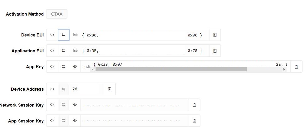
Added DEVICE EUI and APPLICATION EUI as little endian (LSB first).
Coding:
static const u1_t PROGMEM APPEUI[8] = { 0xDE, … 0x70 };
static const u1_t PROGMEM DEVEUI[8] ={ 0xB6, … 0x00 };
static const u1_t PROGMEM APPKEY[16] = { 0x33, … 0x3A, 0x35 };
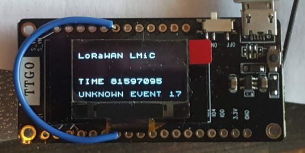
And it does not work. I believe error 17 “something else”.
I compiled PAXCounter from PlatformIO (unknown to PlatformIO, but I eventually managed to upload) and after some time I saw the green button “last seen …few minutes ago”. No payload though, but I am not interested in getting PAXcounter to work, just checking if there is a hardware failure. So there is not.
What am I missing?
[update]
Two screen shots, Unknown Event17 and Join Failed 17.

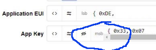
In your above screenshot, the AppKey is displayed in msb. Can you double check that?
The AppKey may probably be the issue here, but my advice is to always start with ABP (ttn-abp.ino) first as this will rule out any possible OTAA issues. If ABP works you know that at least the node (hardware and LMIC) is working.
In the picture you can see it reads LSB, so…
Where can I find the ttn-abp.ino?
Further more… thee are several LMIC libraries out there and I am confused which one to use.
No need to be confused, read the Topic Start.
(If you would need any other version then you will have a specific reason for that.)
Read the Topic Start.
In the picture you can see it reads LSB, so…
I am confused, in your screenshot I am reading MSB, that’s why I said it was worth double checking