This is functionality of the Arduino core for ESP32 and the ESP-IDF. It is independent from the IDE used for development e.g. PlatformIO.
The ‘Arduino platform’ is supported by both the ‘Arduino IDE’ and PlatformIO. The ‘ESP-IDF platform’ is supported by PlatformIO but not by the ‘Arduino IDE’. However, when using the ‘Arduino IDE’ it is possible to call ESP-IDF SDK functions from Arduino code. Arduino core for ESP32 is based on the ESP-IDF SDK. The SDK is included with Arduino core for ESP32.
Hi.
I have a TTGO ESP32 LORA OLED V2 as node with the frequency 868 “https://github.com/matthijskooijman/arduino-lmic” with the example of “ttn-abp.ino”,
I have made the jumpers with cable between DIO2 - GPIO32 (although I have read in some sites is not necessary) AND DIO1 -GPIO33, I modified the att-abp .ino file in the LMIC library with:
I have another TTGO V2 with “https://github.com/things4u/ESP-1ch-Gateway-v5.0” version 5.3.3 “ESP-sc-gway.ino” as gateway to frequency 868.
READY SSID = appears on the screen (my home wifi) and appears on the TTN console as connected.
"Local UDP port = 1700 Connection successful Gateway ID: XXXXXXXXXXXXXX, Listening at SF7 on 868.10 Mhz. setupOta :: Started Ready IP address: 192.168.100.47 Time: Monday 04:33:56 Gateway configuration saved WWW Server started on port 80 OLED_ADDR = 0x3C -------------------------------------- A readUdp :: NTP msg rcvd "
I understand that my gateway is well configured?
The node because I do not receive resouesta?
Sorry, I did not answer your question, I assumed that being a single-channel gateway, I would only have one channel.
I have read about 3 or 4 times, and I will read it again BIG ESP.
So what am I doing wrong, how do I solve it so that the node is understood with the “gateway”?
Compiled from the subject: Frec:868
TTGO LORA ESP32 LORA OLED V2
(ESP-sc-gway.ino v.5.3.3)
ESP-sc-gway.h:
// We support a few pin-out configurations out-of-the-box: HALLARD, COMPRESULT and TTGO ESP32.
// If you use one of these two, just set the parameter to the right value.
// If your pin definitions are different, update the loraModem.h file to reflect these settings.
// 1: HALLARD
// 2: COMRESULT pin out
// 3: ESP32 Wemos pin out
// 4: ESP32 TTGO pinning (should work for 433 and OLED too).
// 5: ESP32 TTGO EU433 MHz with OLED
// 6: Other, define your own in loraModem.h #define _PIN_OUT 4 // TTGO ESP32 LORA OLED V2
oLED.h:
"#elif _PIN_OUT==4||||||||// TTGO (onboard version used, also for DIY)| #define OLED_SCL 22||||||||// GPIO15 // TTGO ESP32 LORA OLED V.2 #define OLED_SDA 21||||||||// GPIO4 // TTGO ESP32 LORA OLED V.2 #define OLED_RST 16||||||||// Reset pin (Some OLED displays do not have it)
Your node will send messages (hop) over different channels, but your single channel gateway can only listen on one single channel so it will miss many of the node’s messages.
If both node and single channel gateway are properly working then you should at least see part of the node’s messages (in TTN console/gateways/<gateway>/traffic and console/applications/<application>/data) but it may take some time before you see them. That time strongly depends on the time between subsequent messages (and you should keep the messages short to prevent possible air-time budget related delays).
It is possible to configure the node so it will use only one single channel. Information for how to do this is already available on the forum but I don’t have a pointer at hand.
For single-channel gateways and related issues (nodes included) the most appropriate thread is: Single Channel Gateway part 3
Hello guys.
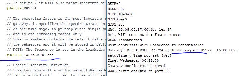
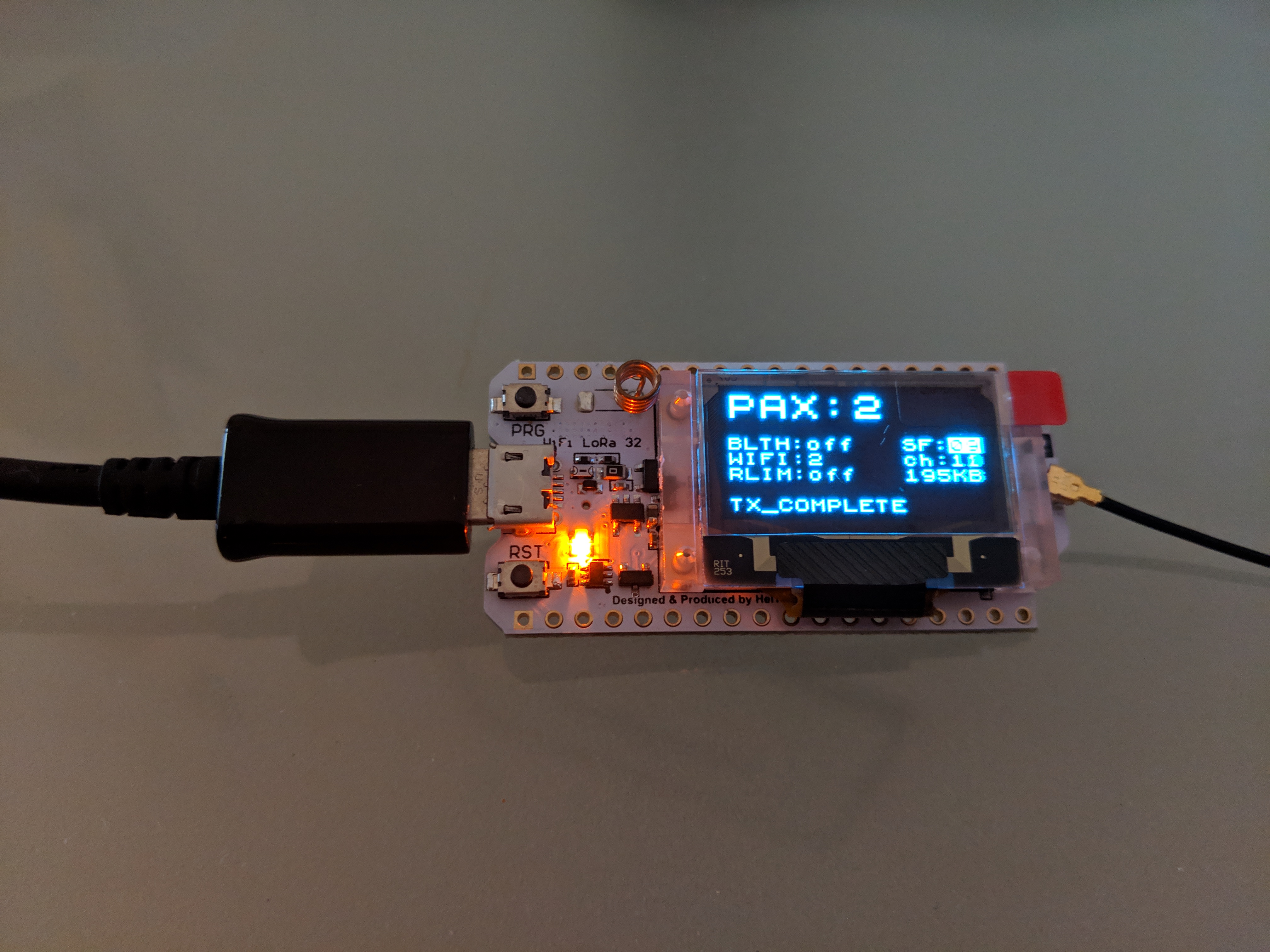
I have 2 Heltec ESP32 LoRa modules connected (no version is shown), so one is a node with one temperature sensor and the other is a gateway connected to the TTN. The problem is that it’s only working for spreading factor 7!
Any other SF that I configure, the Heltec display only shows “READY” and IP (which I am also not able to access as webserver). Weird…
I’m using the matthijskooijman library for 915 MHz.
If I open the serial monitor and reset the gateway, it seems that the settings I make are not having any effect.
Ignore the above problem, guys … hehe
I was having a problem in my network and therefore could not access the webserver, I figured this would not be an impediment to change the spreading factor, but apparently it is only possible to change it online.
I recently got a TTGO T-Beam, same version as quoted above. I was looking a the LDOs used and … the Esp32 is powered by a 150mA LDO! Not good. The markings are 4A2D, which corresponds to a Torex XC6204A regulator. There are 300mA variants (still marginal IMHO) but this is not one of them. Note that there are two such LDO on the board, one for the LoRa module and the GPS, and another for the esp32.
I also noticed that power (whether 5V or LiPo) goes through a TP5400 charger / boost regulator. So on battery the LiPo voltage is boosted to 5v and then regulated down to 3.3v. I’m not expecting decent deep sleep performance like that…
On a positive note, I noticed that the Heltec WiFi Lora V2 schematic shows that the CP2102 USB-serial chip is powered by the 5V bus and not (like all other boards with a CP2102 I’ve seen) by the 3.3v bus. That should remove the dreaded 6.5mA consumption when on battery… I don’t have one of these so I can’t verify.
@bluejedi here are the config that works for my TTGO Lora V2.1 pcb 1.6 (yep the not so good one)
i got it from paxcount which was the only test working on it at first, i use on platformIO with helftec 32 lora board type.
oled pins are not the same as V1 and V2 also the lora rst wich is 23 instead of 14
// Pins for I2C interface of OLED Display #define MY_OLED_SDA (21) #define MY_OLED_SCL (22) #define MY_OLED_RST U8X8_PIN_NONE
I stumbled across this forum and this topic after picking up a pair of TTGO LoRa32 V2.0 modules. I have got them working with a USB power connection and also a 2000mAh LIPO battery. Battery life is good with OLED on but no WiFi or BT and receiving LoRa every 2 seconds. More than enough for this projects intended use.
Now I need to make up a PCB for them and the one thing that concerns me is the 5V connection appears to show the battery voltage when the battery is connected and the switch is in the ON position.
As there are no schematics for this board and virtually no documentation, I have no idea if there are any blocking devices on the board to protect the 5V input and the battery circuit? I need to know if I can power the board from the 5V connection or not. I could put an ideal diode between my external 5V and the 5V pin but this adds to the cost of parts.
Anyone powered the board from the 5V header pin with a battery connected at the same time?
VBUS (USB +5V) and VBAT (battery+) are connected each via their own B5819W Schottkey diode (and for the battery also the on/off switch in series) to the +5V board pin (which is connected to the input of the XC6504 or ME6211 3.3V voltage regulator on the bottom side).
So both the battery+ and USB +5V are protected from reverse current from the +5V pin. Therefore connecting both a battery and externally supplying +5V to the +5V pin is possible.
If the voltage supplied to the +5V pin is lower than ‘actual battery voltage + B5819W’s forward voltage’ then that will drain the battery. Adding a Schottkey diode between the external power supply and the +5V pin will protect against that. The diode will increase the BOM with less than $0.01 which is not really an issue when the TTGO LoRa32 V2.0 board alone already costs $15.
Thanks (I think similar was available already somewhere higher up in the thread). I will add it to the topic start together with other updates when I update the topic start article.