lora… not lorawan 
2 Likes
any idea what the currentdraw is ?
Current draw shows 0.07A running the default LMiC ttn-otaa sketch with code added to use the OLED display.
So far, I have done nothing to reduce power consumption.
Next steps are to move from Arduino framework to IDF with PlatformIO and then I will look to actively disable WiFi and BLE
ok tnx… 70 Ma is indeed a lot … need to trim that, maybe switch off the OLED when not needed…
@nicbkw Let’s discuss about some explanation on LMIC.
The way LMIC is coded is to check (in loop) for a pin change (software does not support IRQ yet) on each declared .dio pin. Then, if one pin has changed, stack is reading software IRQ register of RFM95. Reading RFM95 IRQ internal register will expose all IRQ available (so all DIO0 … DIO5).
That is why I created my “No DIO” patch (and also because I didn’t had any free I/O). this patch read this register and can work without any DIO pin connected, the con is that on each loop, we do SPI transfer to read IRQ register. It’s not fulltime task but it’s done only during LMIC transmission (send and receive) so it’s not so bad, and works !!!
So if you are using only one DIO pin connected this will do twice the check on same pin
.dio = {26, 26, LMIC_UNUSED_PIN},
so you can leave as follow (same result)
.dio = {26, LMIC_UNUSED_PIN, LMIC_UNUSED_PIN},
Another solution is to OR each DIO pins with diodes to trigger a IRQ on any DIO change (once again this is possible only because LMIC read RFM95 IRQ register on any DIO change. And since they are OR’ed, one will be enough.
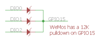
Hope this bring some clarification ![]()
PS : has @jmarcelino will have excellent relationship with pycom, may be he could tell us how DIO are connected on Lopy? We can also open Lopy to see or look into micorpython stack code !
4 Likes
ESP32 is very versatile, has a sophisticated watchdog, but might not be ideal as a very low power data logger.
Of course, this video assumes comms over WiFi…
Thanks very much for this explanation - I was very pleased when @jmarcelino pointed me to your single interrupt polled solution as it works!
Low power and WiFi are not best friends.
Anyway without schematic it’s difficult to know what was consumming. May be his BME280 has 3V3/5V poor regulator conversion (has many) and adding quiescent current ![]()
Would be interesting having current consumption in deep sleep mode
I think he could have tweaked things a little bit.
Even without disabling it, reducing WiFi transmit power would help, the default ( 20 dBm IIRC) causes that sort draw - if you try to do LoRa @ 20 dBm on the SX127x it’s similar.
Also you can lower core clock speed etc. There are many tweaks, and that’s not even involving the ULP which he probably could use for his I2C sensor.
1 Like
Hello,
Pycom’s LoPy uses the SX1272 chip rather than the SX1276 used in this device. A few months ago, I was able to implement a single channel gateway on the ESP32 and with the RFM95W LoRa Module by porting Pycom’s code for their Lopy, inserting libraries for the SX1276 and modifying the code to achieve this. If interested, the source code is available from github here https://github.com/aizukanne/micropython-lora.
The pinouts are hard coded in the pycom firmware code but you can make changes. On the Lopy RADIO_DIO is connected to GPIO23. You will need to change this to GPIO26 to match this device. All other connections are same. The LoPy firmware does not use a reset for ESP32 chip revision > 0. My port was for chip revision > 0. Pin connections for chipset = 0 is different.
I implemented a single channel gateway using the pycom script for that as available here https://github.com/pycom/pycom-libraries/tree/master/examples/lorawan-nano-gateway.
ABP works but OTAA didnt seem to work. I haven’t been able to sort that out. Hope someone will be able to.
Do give it a try.
7 Likes
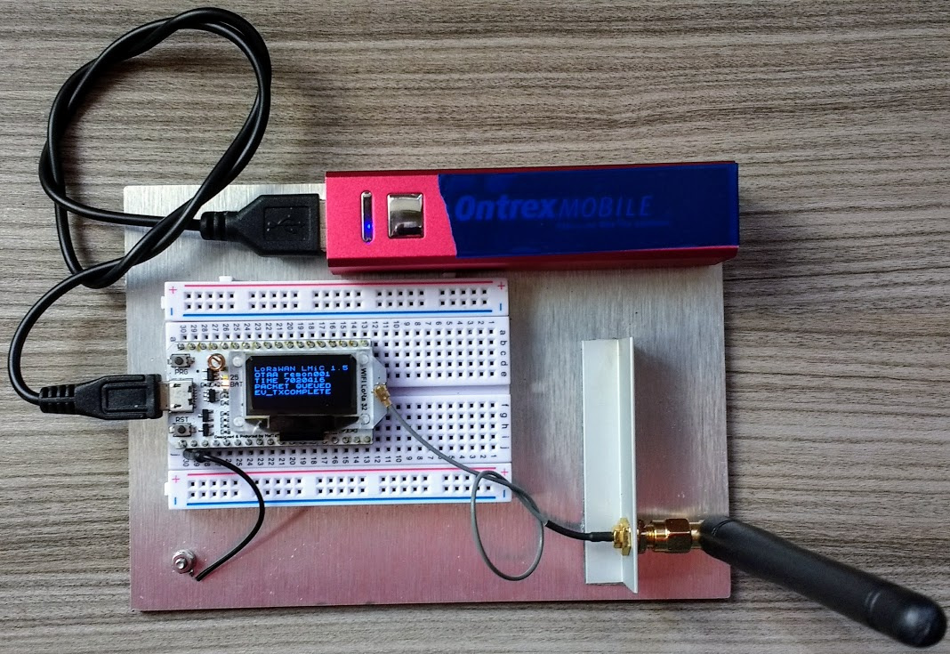
HELTEC HTIT-WB32LA 868-915 MHz board
I just received the board.
After examining the PCB I found that the following DIO ports are wired:
(pin numbers are chip pin numbers)
SX1276 (pin) – ESP32 (pin)
DIO0 (8) – GPIO26 (15)
DIO1 (9) – GPIO33 (13)
DIO2 (10) – GPIO32 (12)
Hope this helps.
3 Likes
If you want to use those USB power banks, be aware that they can reate a fair bit of EMI, take a read of this;
3 Likes
Thanks for this reminder - I will compare with a LiPo
I admire your patience and visual acuity
Thanks!
1 Like
So I received that SX1278 / 433Mhz one I ordered by error : https://fr.aliexpress.com/item/SX1278-LoRa-ESP32-0-96-inch-Blue-OLED-Display-Bluetooth-WIFI-Lora-Kit-32-Module-Internet/32831131677.html?isOrigTitle=true
Anyone in an appropriate region to use it who wants it, I’ll send it for the cost of shipping - from France.
Edit : no longer available, it went to someone in Germany.
1 Like
@nicbkw and Heltec 868 MHz users,
Anyone made a ready to use package or published a github with the Arduino code and libraries for testing the Heltec 868 MHz device with LoRaWAN?
Cheers.
OK, I got my Heltec LoRa boards today. No secret, I am not a programmer but I have tried to duplicate what you have done to make the libraries work… I can’t get it to work!
First issue I have is the declaration in oslmic.h , it is done per your hint but I get a compile error.
C:\Users\Garry\Documents\Arduino\libraries\arduino-lmic-master\src\hal\hal.cpp: In function ‘void hal_io_check()’:
C:\Users\Garry\Documents\Arduino\libraries\arduino-lmic-master\src\hal\hal.cpp:66:32: error: ‘radio_has_irq’ was not declared in this scope
         if ( radio_has_irq() )

                            ^
Would you have a suggestion what I have done wrong? I have declared it below…
// Dependencies required for the LoRa MAC in C to run.
// These settings can be adapted to the underlying system.
// You should not, however, change the lmic.[hc]
…at line 83, is this glaringly wrong?
Thanks, Garry
Hi - just use https://github.com/matthijskooijman/arduino-lmic and set Pin mapping like this (thanks to @bluejedi)
// Pin mapping
const lmic_pinmap lmic_pins = {
    .nss = 18,
    .rxtx = LMIC_UNUSED_PIN,
    .rst = 14,
    .dio = {26, 33, 32},
};
Mapping all 3 DIO pins means there is no need to change the LMiC library as I described.
3 Likes
@nicbkw Much obliged for your help, first attempt at OTAA and with the new ESP32 board. Now to wade out of my depth with some sensors and possibly even the OLED! Thanks again…
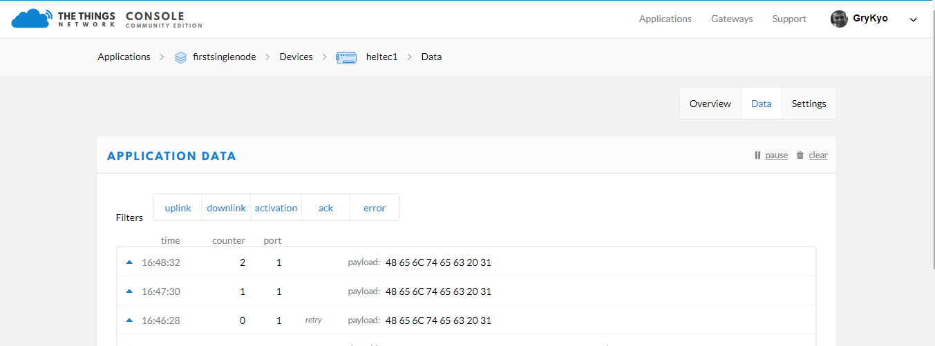
Garry
1 Like