Meric,
can you tel me what finally solved the issue?
I’m struggling for days now with the problem you described.
I have the 1.2 board and made the solder as in the picture.
I run the ttn-otta example(added LMIC_setClockError(MAX_CLOCK_ERROR * 1 / 100);).
Replaced the EUI’s(lsb) and APPKEY(msb) with my own values.
In my application on TTN I see that the Activation message is received, but than nothing further happens.
I have been reading this topic with great interest but I am getting more and more confused; probably due to my ignorance.
I have recently ordered to LoRa32u4 II v1.2 boards and am struggeling to get them to work. I have used the libraries etc. from the bsfrance.fr website.
I do not have access to the Things Network where I live in the Dutch countryside, all gateways are too far away.
My confusion:
I can select the correct board (868 MHz flavour) in the Arduino IDE, but the IDE says I have a 433MHz board
My assumtion is that when I upload the “sender” and “receiver” examples I should see incoming packets on the receiver board through the serial monitor. I get nothing.
do I need to solder a kind of bypass on these new boards to get them to work?
Both boards are powered through USB; one with a power supple (the sender) the other through my Linux PC so that I can see the output on the serial monitor.
Eventually I want to create a sensor network on a big farm in Africa I work with, collecting data like soil temperature, air temperature, soil humidity, air humidity, CO2 levels etc. The number of nodes can be big: up to hundreds.
For now I want to develop a simple proof of concept where I can send data from one node to the other, following MQTT messaging to a server when that is established etc.
For the big picture I will need a serious gateway, for the proof of concept only a few of these boards.
there is a big difference between one 'node. transmitting a temp and one node listening on your desk and a 'serious test setup with at least 50 nodes transmitting data from multiple sensors (at the same time) and your backend server setup and application(s) to manage this dataflow and nodes.
this is not the forum for point to point basic LoRa communication.
if you search github you’ll find many code examples, also maybe this article is interesting for you
I see in the BSFrance description that the LiPo charger charges at 100mA but can be set up to 1A by resistor. However, I did not find how to do it (2000mAh to charge becomes very long). Ideas? (suitable for a bad solderer like me ). Thanks.
I think the bsfrance board schematic would pretty much match the one at adafruit. Adafruit may have a note on what to change and what value to use. It’s probably a surface mount resistor. I’m guessing, but increasing the current to 1 Amp will overload a typical USB port when plugged in.
Thanks for the suggestion: in fact here I found schematics with some indication. 500mAh could be better suited for charging - or even 200 if needed. Now let’s guess where is the resistor
Good luck, my board seems to be painted black, so no reference marks. There are two 5 pin chips next to the reset button. Between them is a tiny 10K resistor. This may be the one you need to change. It appears to supply a reference voltage to the charger, kinda like an lm317 regulator. I suspect that it maintains a constant voltage across that resistor when it is charging, and then the voltage disappears when the charge light goes out. You could test my theory with a DMM, but it’s really tight in there. You could solder another 103 on top of it and double the charge current, assuming that’s the right resistor.
Edit:. You could put a 5k (502) on top and triple the charge current to 300mA. Stacking seems easier than replacement.
Hello, I have this strange problem with several of my v1.2 bsfrance boards.
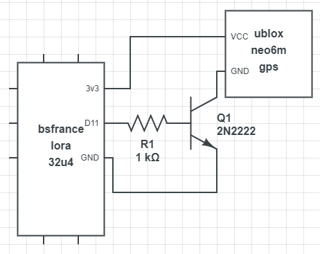
I’m using 2n2222 to switch power to gps on/off. this works well when powered via usb, but when powered through battery the board just flashes and never starts doing anything… (constant bootloop or something) It works well on my v1.1 boards and it works well on my pro minis. I thought it might be some code error so I wrote a small test program to set pin D11 high to power the GPS. Still the same. The code actually sets pin D11 high also on battery (I have measured), but as soon as the resistor, 2N2222 and GPS setup is connected the board starts to flash and D11 looses power.
I have tried with both with 1k ohm and 390 ohm resistor. And also with several 2n2222.
The neo6m GPS draws something between 40-70mA
Anyone else tried to use npn to switch something with the v1.2 board?
arduino testcode:
// ************************************
const int GPSPowerPin = 11;
void setup() {
// put your setup code here, to run once:
pinMode(GPSPowerPin, OUTPUT);
}
void loop() {
// put your main code here, to run repeatedly:
Have you tried simply connecting your ublox directly to the board’s 3v3 and GND while battery powered (no sketch) to see if it is overloading the board’s regulator? Like this would the ublox be stable? Does the ublox work on an other supply?
It may be nothing to do with your sketch, possibly a bad/cheap/wrong regulator or possibly a high resistance somewhere.
Have you tried SMD rework before? You may need to change the regulator on the board…
I have not tried connecting GPS directly to the 3v3 output of this v1.2 board, but on a v1.1 board and a pro mini. I can give it a try, but the datasheet states max output of 600mA on the 3v3 LDO (I assume that means the 3v3 pin) And it also says max 20mA, recommended 10mA on any IO-pin. I have calculated the current through D11 to the 2n2222 to be in the area 4-6mA.
The ublox works when the board is powered through USB. Actually the whole powerswitching setup works while powered through usb. So far I have tried two of my v1.2 boards with the same batterypowered problem. Of course it could be a bad regulator on both, but isn’t it the same regulator that regulates the 5v usb power?
I have not tried any SMD work before, and would like to explore other possibilities before replacing the regulator.
Tried powering it dircetly from 3v3 and GND while measuring current to 60mA. Did however not manage to get GPS-fix and the behaviour was a bit strange as it sometimes tried to send position every 10 seconds (was set to 2 min)
I now remember that the last time I successfully used battery was with a C-cell 1,5V stepped up to 3v3.
Now I am using ER14505 3,6V battery. Perhaps it has trouble delivering enough current.
While GPS is directly connected to 3v3 and GND and board powered battery, I measure the D11 pin to 2,7V. (nothing connected to it, just set high in code) The same pin is measured to 3,25V when I power the board through usb.
I think my next step is to find a better battery to see if that makes any difference…
(FYI I’m trying to make a tiny tracker to make it easier to find my sheeps in the mountain after summer…)
 ). Thanks.