Hi, I am using a ttgo T3_V1.6 module with MCCI LoRaWAN LMIC librari example and only ttn-abp works for me.
When using the ttn-otaa example I get the error EV_JOIN_TXCOMPLETE: no JoinAccept.
And in TTN only 1 data with a yellow ray.
thanks
Is it ensured that the downlink from the gateway works in principle?
I see messages transmitted by the gateway, therefore I suppose that it works. How can I check?
I guess the messages are not received in time by the node. ESP32 are typically pretty bad in OXCO Accuracy.
Try to add the following lines in your setup
LMIC_setClockError(MAX_CLOCK_ERROR * 10 / 100);
Source is https://www.thethingsnetwork.org/forum/t/need-help-with-mcci-lmic-and-ttn-join-wait-issue/30846
And to speed up joining progress: Open your node in the console and press the “Reset Frame Counter”
Then restart your node.
Joining may take time. Up to 20 Join Requests are pretty normal on a ESP32. It depends on your SNR.
That does nothing for OTAA. A join automatically resets the frame counter.
I can’t confirm this. I tested a lot of different ESP32 based boards with MCCI LMIC and join problems do not correlate with either board or Clockerror setting.
1 Like
OTAA will fail if downlink messages are not working (properly) which is usually caused bij either one of the following:
- Incorrect (DIO1) pin mapping (or not connected).
- Timing issues.
What are your LMIC pin mappings?
Have you verified that these are set correctly for your board?
Hi, I´m having a similar stuggle and I really hope someone can help me to figure this out.
I did eveything I´ve found in the forum but I cannot make it work.
I´m using TTGO LoRa OLED v1 with the same library as Jorfevi, the MCCI LoRaWAN LMIC.
ttn-abp example works good for me, I have a Pycom nanogateway in the same room and messages are received in the TTN console.
Where I am having lots of problems is with the ttn-otaa example, I get:
EV_JOIN_TXCOMPLETE: no JoinAccept.
I´ve waited a couple of hours but it keeps on showing the same message.
I have already:
-
Checked mapping for the board (actually works because with ABP example works fine)
-
added line
LMIC_setClockError(MAX_CLOCK_ERROR * 10 / 100);`
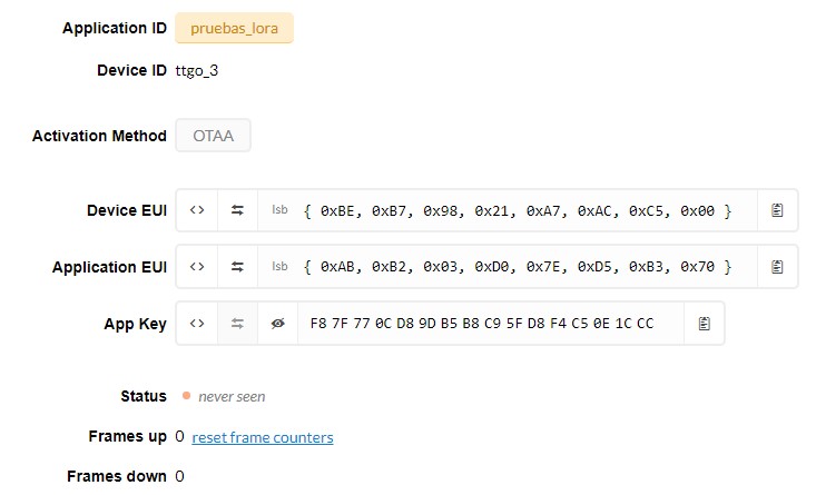
- OTAA keys are in the correct order
#include <lmic.h>
#include <hal/hal.h>
#include <SPI.h>
//
// For normal use, we require that you edit the sketch to replace FILLMEIN
// with values assigned by the TTN console. However, for regression tests,
// we want to be able to compile these scripts. The regression tests define
// COMPILE_REGRESSION_TEST, and in that case we define FILLMEIN to a non-
// working but innocuous value.
//
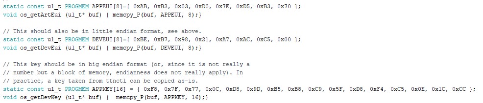
// This EUI must be in little-endian format, so least-significant-byte
// first. When copying an EUI from ttnctl output, this means to reverse
// the bytes. For TTN issued EUIs the last bytes should be 0xD5, 0xB3,
// 0x70.
static const u1_t PROGMEM APPEUI[8]={ 0xAB, 0xB2, 0x03, 0xD0, 0x7E, 0xD5, 0xB3, 0x70 };
void os_getArtEui (u1_t* buf) { memcpy_P(buf, APPEUI, 8);}
// This should also be in little endian format, see above.
static const u1_t PROGMEM DEVEUI[8]={ 0xBE, 0xB7, 0x98, 0x21, 0xA7, 0xAC, 0xC5, 0x00 };
void os_getDevEui (u1_t* buf) { memcpy_P(buf, DEVEUI, 8);}
// This key should be in big endian format (or, since it is not really a
// number but a block of memory, endianness does not really apply). In
// practice, a key taken from ttnctl can be copied as-is.
static const u1_t PROGMEM APPKEY[16] = { 0xF8, 0x7F, 0x77, 0x0C, 0xD8, 0x9D, 0xB5, 0xB8, 0xC9, 0x5F, 0xD8, 0xF4, 0xC5, 0x0E, 0x1C, 0xCC };
void os_getDevKey (u1_t* buf) { memcpy_P(buf, APPKEY, 16);}
static uint8_t mydata[] = "Hello, world!";
static osjob_t sendjob;
// Schedule TX every this many seconds (might become longer due to duty
// cycle limitations).
const unsigned TX_INTERVAL = 60;
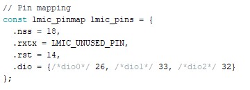
// Pin mapping
const lmic_pinmap lmic_pins = {
.nss = 18,
.rxtx = LMIC_UNUSED_PIN,
.rst = 14,
.dio = {/*dio0*/ 26, /*dio1*/ 33, /*dio2*/ 32}
};
void printHex2(unsigned v) {
v &= 0xff;
if (v < 16)
Serial.print('0');
Serial.print(v, HEX);
}
void onEvent (ev_t ev) {
Serial.print(os_getTime());
Serial.print(": ");
switch(ev) {
case EV_SCAN_TIMEOUT:
Serial.println(F("EV_SCAN_TIMEOUT"));
break;
case EV_BEACON_FOUND:
Serial.println(F("EV_BEACON_FOUND"));
break;
case EV_BEACON_MISSED:
Serial.println(F("EV_BEACON_MISSED"));
break;
case EV_BEACON_TRACKED:
Serial.println(F("EV_BEACON_TRACKED"));
break;
case EV_JOINING:
Serial.println(F("EV_JOINING"));
break;
case EV_JOINED:
Serial.println(F("EV_JOINED"));
{
u4_t netid = 0;
devaddr_t devaddr = 0;
u1_t nwkKey[16];
u1_t artKey[16];
LMIC_getSessionKeys(&netid, &devaddr, nwkKey, artKey);
Serial.print("netid: ");
Serial.println(netid, DEC);
Serial.print("devaddr: ");
Serial.println(devaddr, HEX);
Serial.print("AppSKey: ");
for (size_t i=0; i<sizeof(artKey); ++i) {
if (i != 0)
Serial.print("-");
printHex2(artKey[i]);
}
Serial.println("");
Serial.print("NwkSKey: ");
for (size_t i=0; i<sizeof(nwkKey); ++i) {
if (i != 0)
Serial.print("-");
printHex2(nwkKey[i]);
}
Serial.println();
}
// Disable link check validation (automatically enabled
// during join, but because slow data rates change max TX
// size, we don't use it in this example.
LMIC_setLinkCheckMode(0);
break;
/*
|| This event is defined but not used in the code. No
|| point in wasting codespace on it.
||
|| case EV_RFU1:
|| Serial.println(F("EV_RFU1"));
|| break;
*/
case EV_JOIN_FAILED:
Serial.println(F("EV_JOIN_FAILED"));
break;
case EV_REJOIN_FAILED:
Serial.println(F("EV_REJOIN_FAILED"));
break;
case EV_TXCOMPLETE:
Serial.println(F("EV_TXCOMPLETE (includes waiting for RX windows)"));
if (LMIC.txrxFlags & TXRX_ACK)
Serial.println(F("Received ack"));
if (LMIC.dataLen) {
Serial.print(F("Received "));
Serial.print(LMIC.dataLen);
Serial.println(F(" bytes of payload"));
}
// Schedule next transmission
os_setTimedCallback(&sendjob, os_getTime()+sec2osticks(TX_INTERVAL), do_send);
break;
case EV_LOST_TSYNC:
Serial.println(F("EV_LOST_TSYNC"));
break;
case EV_RESET:
Serial.println(F("EV_RESET"));
break;
case EV_RXCOMPLETE:
// data received in ping slot
Serial.println(F("EV_RXCOMPLETE"));
break;
case EV_LINK_DEAD:
Serial.println(F("EV_LINK_DEAD"));
break;
case EV_LINK_ALIVE:
Serial.println(F("EV_LINK_ALIVE"));
break;
/*
|| This event is defined but not used in the code. No
|| point in wasting codespace on it.
||
|| case EV_SCAN_FOUND:
|| Serial.println(F("EV_SCAN_FOUND"));
|| break;
*/
case EV_TXSTART:
Serial.println(F("EV_TXSTART"));
break;
case EV_TXCANCELED:
Serial.println(F("EV_TXCANCELED"));
break;
case EV_RXSTART:
/* do not print anything -- it wrecks timing */
break;
case EV_JOIN_TXCOMPLETE:
Serial.println(F("EV_JOIN_TXCOMPLETE: no JoinAccept"));
break;
default:
Serial.print(F("Unknown event: "));
Serial.println((unsigned) ev);
break;
}
}
void do_send(osjob_t* j){
// Check if there is not a current TX/RX job running
if (LMIC.opmode & OP_TXRXPEND) {
Serial.println(F("OP_TXRXPEND, not sending"));
} else {
// Prepare upstream data transmission at the next possible time.
LMIC_setTxData2(1, mydata, sizeof(mydata)-1, 0);
Serial.println(F("Packet queued"));
}
// Next TX is scheduled after TX_COMPLETE event.
}
void setup() {
Serial.begin(9600);
Serial.println(F("Starting"));
#ifdef VCC_ENABLE
// For Pinoccio Scout boards
pinMode(VCC_ENABLE, OUTPUT);
digitalWrite(VCC_ENABLE, HIGH);
delay(1000);
#endif
// LMIC init
os_init();
// Reset the MAC state. Session and pending data transfers will be discarded.
LMIC_reset();
// Disable link check validation
LMIC_setLinkCheckMode(0);
LMIC_setClockError(MAX_CLOCK_ERROR * 10 / 100);
// TTN uses SF9 for its RX2 window.
LMIC.dn2Dr = DR_SF9;
// Set data rate and transmit power for uplink
LMIC_setDrTxpow(DR_SF7,14);
// Start job (sending automatically starts OTAA too)
do_send(&sendjob);
}
void loop() {
os_runloop_once();
}
Just in case, here is my code. I´ve been working with this for the last couple of days but I can´t have any success. I´ll really appreciate your help!
First, do downlinks work OK for ABP - this will confirm that your device is able to hear messages and indicate if the timing is correct.
Second, if you have the device & gateway too close, the transmission may overwhelm the receiver - they should preferably be 5-10m apart or in another room, or both.
2 Likes
@descartes thank you very much for you reply.
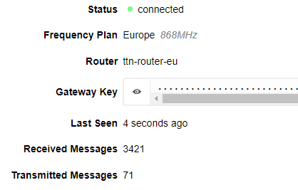
This image is from the gateway. The strange thing (if you can give me some light here) is that the uplink is in 916.8 mHz and the downlink in 923.3, does that have something to do with the gateway?
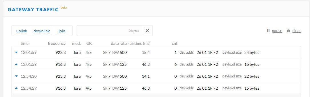
Gateways aren’t the brightest boxes in the world - they pass on things they hear and do as the network server says, so the right device, gateway & network server for a region all have to be configured. I’m assuming from the frequencies used that you are using an Australian band plan - which I’m aware has complications but I’m not very familiar with as I’m in the UK.
You’ll see on https://www.thethingsnetwork.org/docs/lorawan/frequency-plans.html a mention of:
“Note that The Things Network uses 2nd Sub-Band only (channels 8 to 15 and 65). You’ll need to program the specific channels into the devices in order to make them work with TTN.”
The MCCI LMiC documentation has information on settings for regions so there may be some detail to dig in to there.
1 Like
Thank you very much Nick for your responses, I´m going to dive into it right now. If it works for me I´ll mention it here.
Best!
FYI: ‘TTGO LoRa OLED v1’ is the name of a board definition for TTGO LoRa and TTGO LoRa32 boards but is not the product name and version of a board.
Unfortunately there is only a single board definition for these boards while there are many different versions of the TTGO LoRa32 boards (e.g. V1.0, V1.3, V2.0, V2.1.5, V2.1.6).
Please (also) specify the exact name including version of your board.
(It is important to provide as much essential details as possible.)
You used above pin mapping so apparently you have some V2.x and not a V1.x board.
For TTGO LoRa32 V2.0 only DIO0 is (hard-)wired onboard and you will need to manually wire (connect) DIO1 to GPIO33 (for LoRa DIO2 is not needed).
For V2.1.6 (according to another forum user) DIO0, DIO1 and DIO2 are all (hard-)wired onboard by default. For V2.1.5 I’m not sure.
Above DIO1 and DIO2 information is lacking from LilyGO documentation (which is known to be poor and incomplete).
1 Like
You have not mentioned but appear to have set AU915 as your region.
The different frequencies for uplinks and downlinks shown on the console match the frequencies listed for AU915-923 in TTN’s frequency plans documentation.
So the frequencies shown appear to be correct.
1 Like
Above documentation for AU915-928 is not clear and appears incomplete or incorrect. It lists only uplink channels 1 to 9 and downlink channels 1 to 9. Details for the other channels mentioned are missing.
Also not clear is if setting of channels 8 to 15 and 65 is required for both ABP and OTAA or for ABP only (and set automatically when using OTAA).
Does the text ‘programming of channels 8 to 15 and 65’ still apply or is this outdated?
Maybe @johan can elaborate on the above?
MCCI LMIC v3.3.0 documentation shows:
For any region, there are some channels that cannot be modified (the “default channels”). You can’t disable or change these, but it’s not an error to try to set a default channel to its default value.
Some regions (such as US915 or AU915) do not allow any channels to be set up.
Above conflicts with mentioned TTN requirement for setting up ‘other’ channels for AU915.
MCCI LMIC v3.3.0 README.md shows:
us915, au915
If the library is configured for US915 operation, we make the following changes:
- Add the APIs
LMIC_enableChannel(),LMIC_enableSubBand(),LMIC_disableSubBand(), andLMIC_selectSubBand().- Add the constants
MAX_XCHANNELS.- Add a number of additional
DR_...symbols.
Both us915 and au915 are listed in the header, so apparently
If the library is configured for US915 operation
is incomplete and should probably read the following
If the library is configured for US915 or AU915 operation:
I was unable to find any mentioning of ‘programming specific channels (8 to 15 and 65) for AU915 to make it work with TTN’ in above MCCI LMIC documents.
It appears that to use MCCI LMIC with TTN in the AU915 region, only requires to set AU915 as region (without having to set specific channels as suggested in the TTN documentation):
Selecting the LoRaWAN Region Configuration
The library supports the following regions:
-DvariableCFG region name CFG region value LoRaWAN Regional Spec 1.0.3 Reference Frequency -D CFG_au915LMIC_REGION_au9155 2.6 Australia 915-928 MHz ISM
Which is correct here, the TTN documentation or the MCCI LMIC documentation and in which is relevant information missing?
1 Like
Hi
I am having the same issue with connecting OTAA . node is receiving and transmitting data using gateway with ABP but its not working with OTAA. Please anyone can help to sort this out
Thanks in Advance
1 Like
did you find a solution for this ?
your APPEUI and DEVEUI are not correct. They should be in reverse format (each one of them). 
igrone my above comment. I’ll post working code in 2 days. I have it working for heltec LORA esp32 OLED v2 board
There is working code with documentation available that supports both TTGO and Heltec boards (and more) out of the box:
1 Like