Hello , can i get a tips & trick for decode a simple analog reading ?
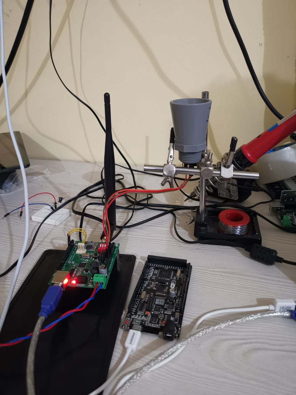
I’m use maxbotix sensor, it’s perfectly reading with standalone arduino board, but not succesfull when hook up to TTN , i guess i’m missing with the decoder function
Does anyone can give tips & trick working with decoder?
While “not successful” and a photo are, of course, not enough to help, a Payload Format/decoder is not mandatory so that’s unlikely to cause whatever problems you’re having.
I’d first make sure that data is received on the gateway(s) and in your application, and when that works then see Payload Formats [HowTo] for some details on the decoder.
The LMIC code you’re showing is not related to your screenshots of TTN Console.
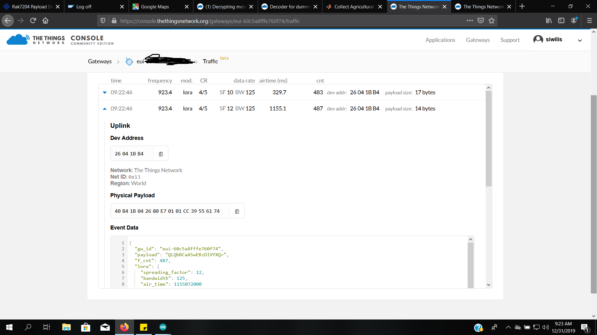
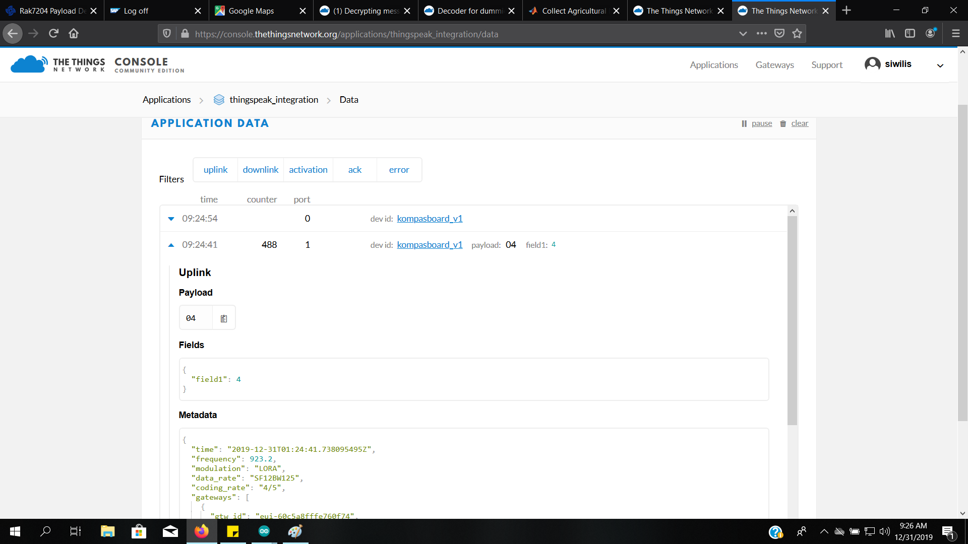
In TTN Console the device with DevAddr 0x26041BB4 receives just one byte. The code is for a different DevAddr, and sends 2 bytes:
static const u4_t DEVADDR = 0x26041EC8 ;
...
void do_send(osjob_t* j){
    // Payload to send (uplink)
    static uint8_t message[2];

    int value = analogRead(A0);
    message[0] = highByte(value);
    message[1] = lowByte(value);

    // Check if there is not a current TX/RX job running
    if (LMIC.opmode & OP_TXRXPEND) {
        Serial.println(F("OP_TXRXPEND, not sending"));
    } else {
        // Prepare upstream data transmission at the next possible time.
        LMIC_setTxData2(1, message, sizeof(message), 0);
        Serial.println(F("Sending uplink packet..."));
    }
    // Next TX is scheduled after TX_COMPLETE event.
}
Also, this code is not printing anything to the serial monitor; there’s no Serial.println(value) in that code.
So, first: upload the right sketch to your Arduino board.
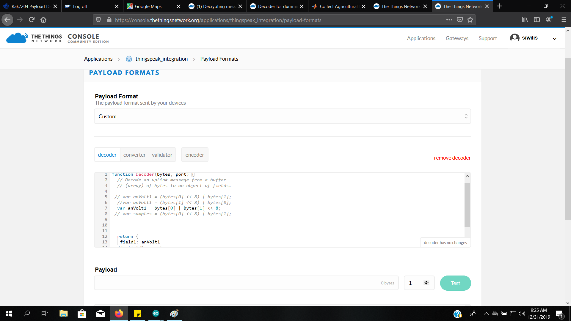
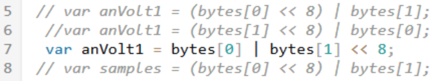
Next: the code, which is using message[0] = highByte(value), encodes the MSB first, so when decoding the value in bytes[0] needs to be shifted 8 bits to the left. In your decoder you’ve used a different order. For the Arduino sketch that you’ve linked to, the decoder should use line 5 (and the parentheses are not needed):
(Please don’t post screenshots for code! And please crop screenshots to the relevant parts. Thanks.)