Full Arduino Mini LoraWAN below 1uA Sleep Mode

Hi Guys,

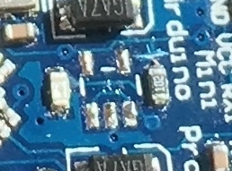
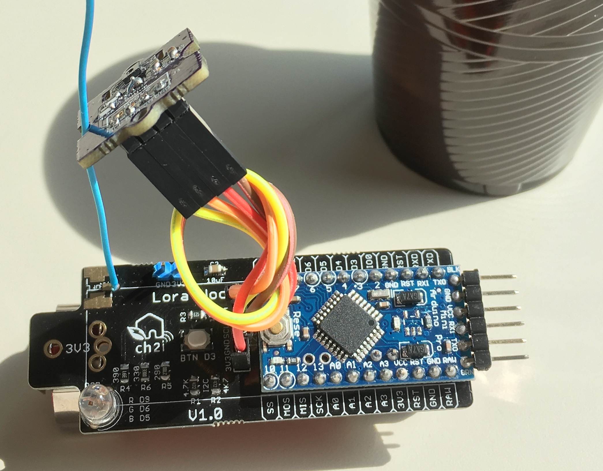
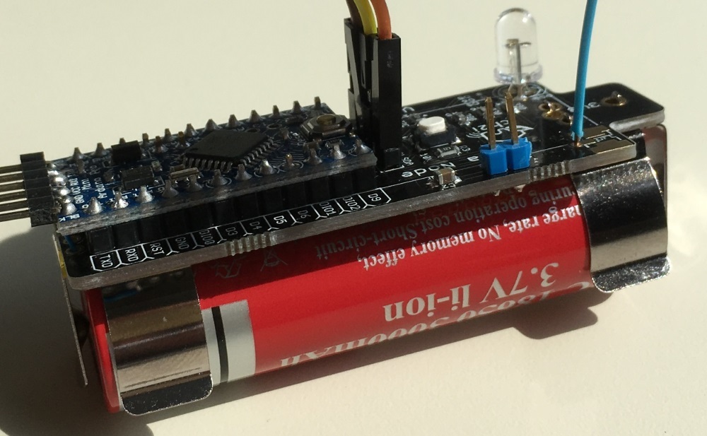
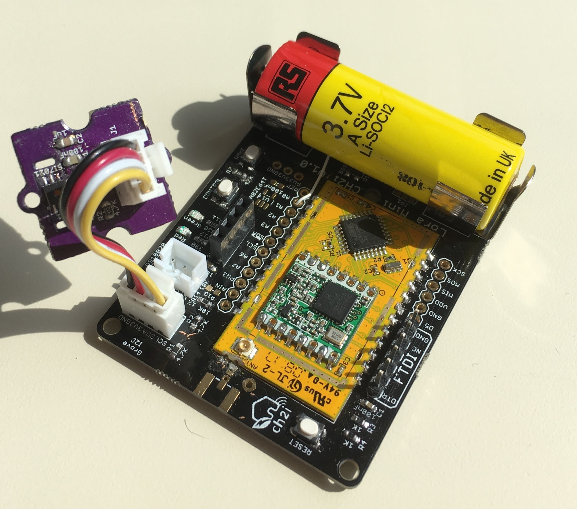
I’d like to introduce my new demo node, no wire, just battery powered, Arduino Mini 3.3V 8Mhz. I created a demo for a customer with a fully Temperature Humidity sensor (I2C SI7021) with Battery Level Monitor, and here it is.

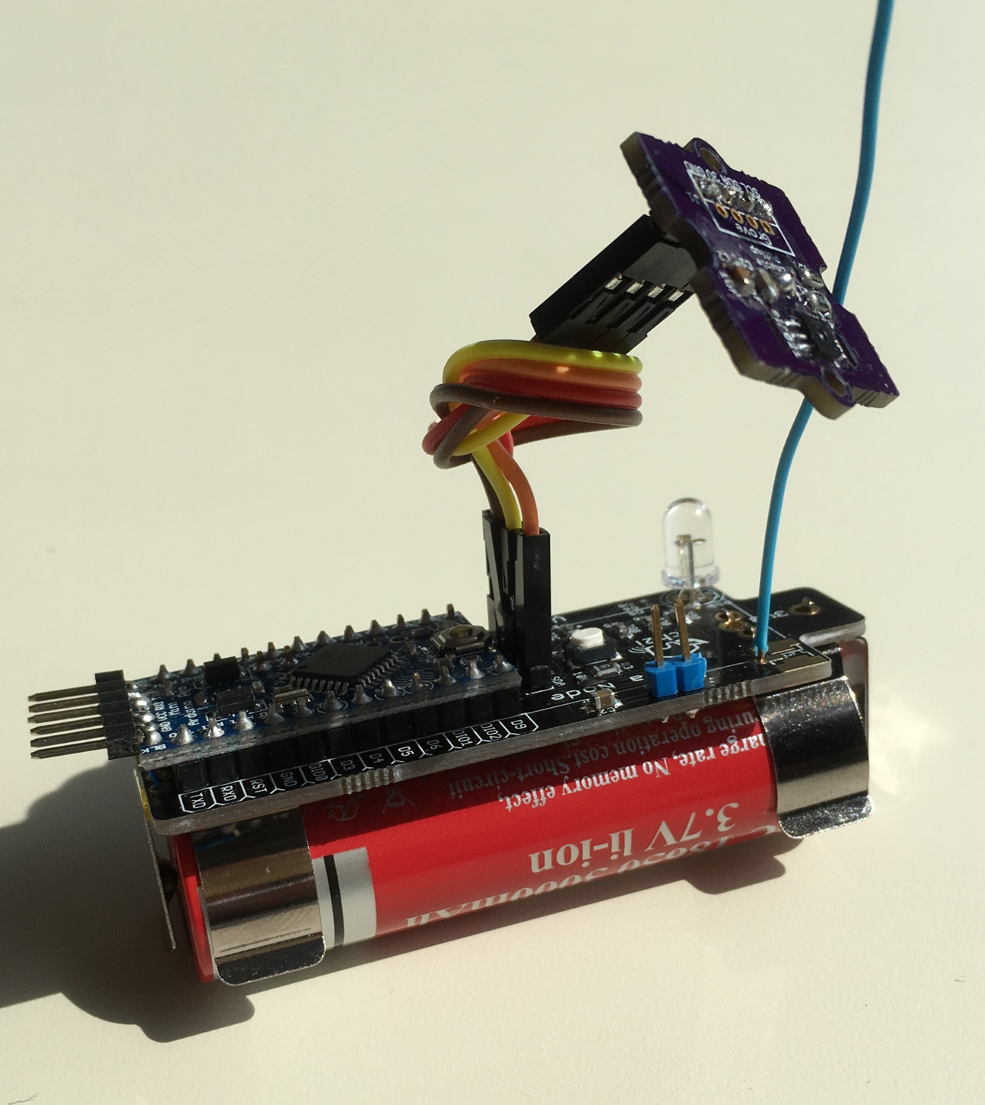
I know it’s not the smallest node, but what the deal with small nodes if the battery size is twice the node size?
So I decided to test some with battery and my old ULPNode Power Efficient Library (not released yet but soon) but trust me this library is amazing for low power hand have plenty API and tricks -).

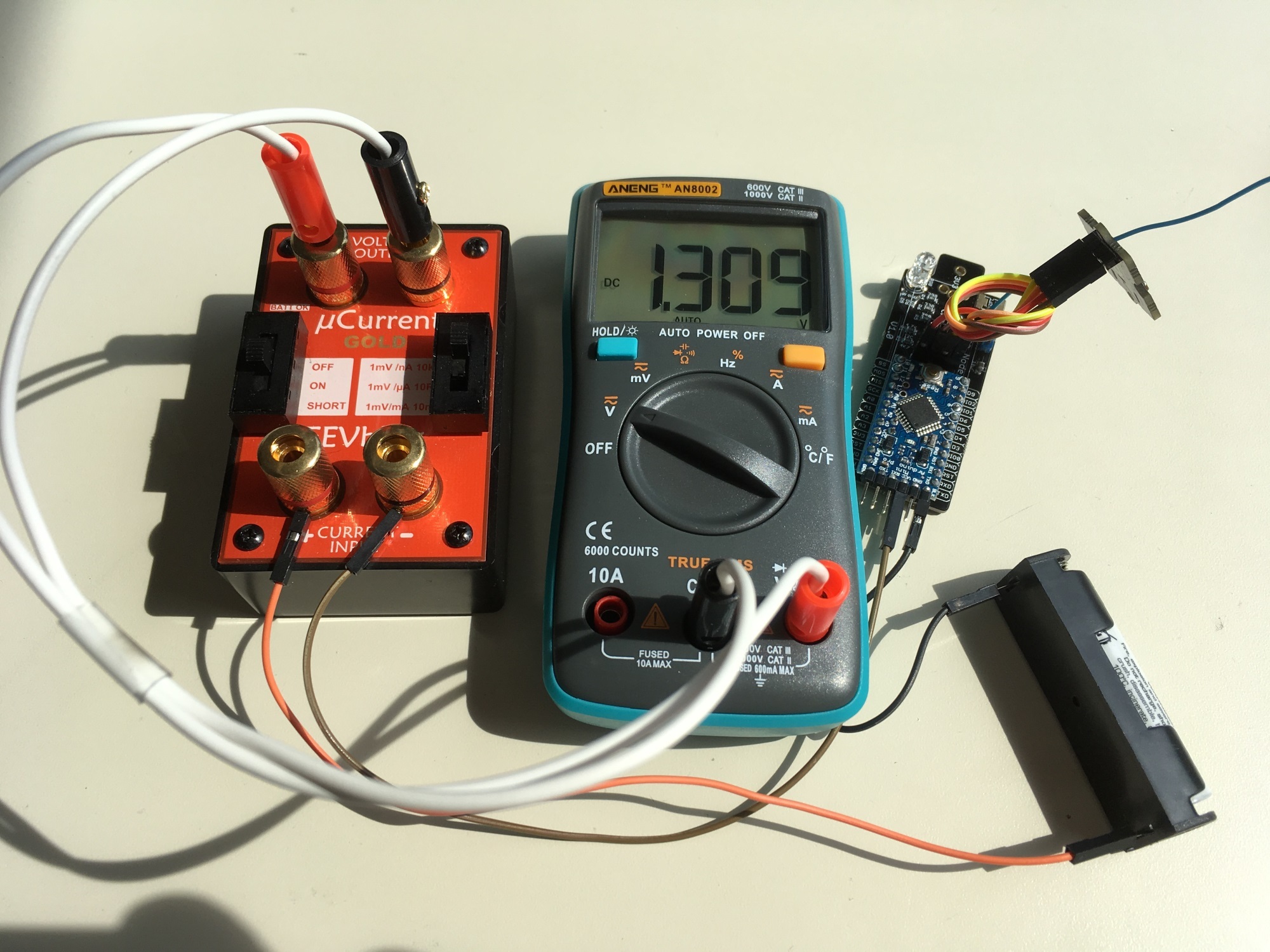
Okay, so what? Consumption in sleep mode?
1.3uA, not bad at all

So how I made this? What I’ve done?

  • I changed hardware definition in my library to reflect new one (no more ULPNode Hardware, just Nano Mini where I removed power LED of course)
  • Changed ULPNode RF Protocol so conform Cayenne LPP, strange it’s mostly the same I created (see section payload sensor data), looks like the idea was not too bad
  • Lightened the ULPNode library (now called ULPNodeLight), no more RFM69 with RadioHead but RFM95 and LMIC
  • Created a config sketch tu put EUID on EEP instead having them on code
  • Use Device ID located into I2C EEP Microchip 24AA02E64T (on board chip) if found
  • Adapted OTAA sample with ULPNode Library and Low Power Management
  • Use of one button press to do different action such as ACK or Not, Wake Duration, …
  • Added LED to confirm all is fine (for testing, not very lowpower of course)
  • Flashed Arduino Mini with Optiboot bootloader (win 1.5K of code) and decreased Brown Out detection to 1.8V to see how far we can go with RFM95. I created basic PCB programmer adapter and bootloaders for this purpose.

And final results, after going thru TTN Gateway, TTN Backend, here them with Cayenne Integration

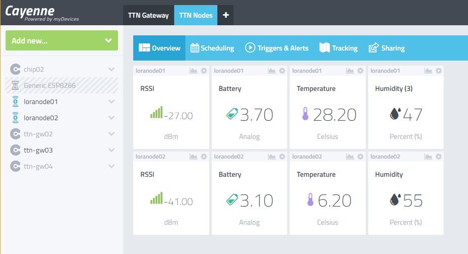
Cayenne Integration with TTN is a must, widgets comes on dashboard immediately after receiving 1st LPP frame, amaaaaaaazing !!

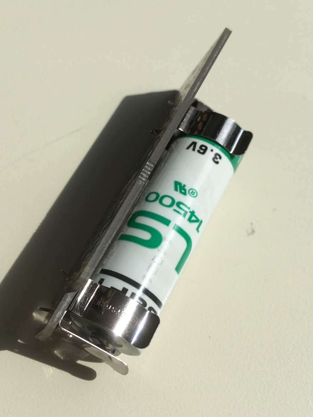
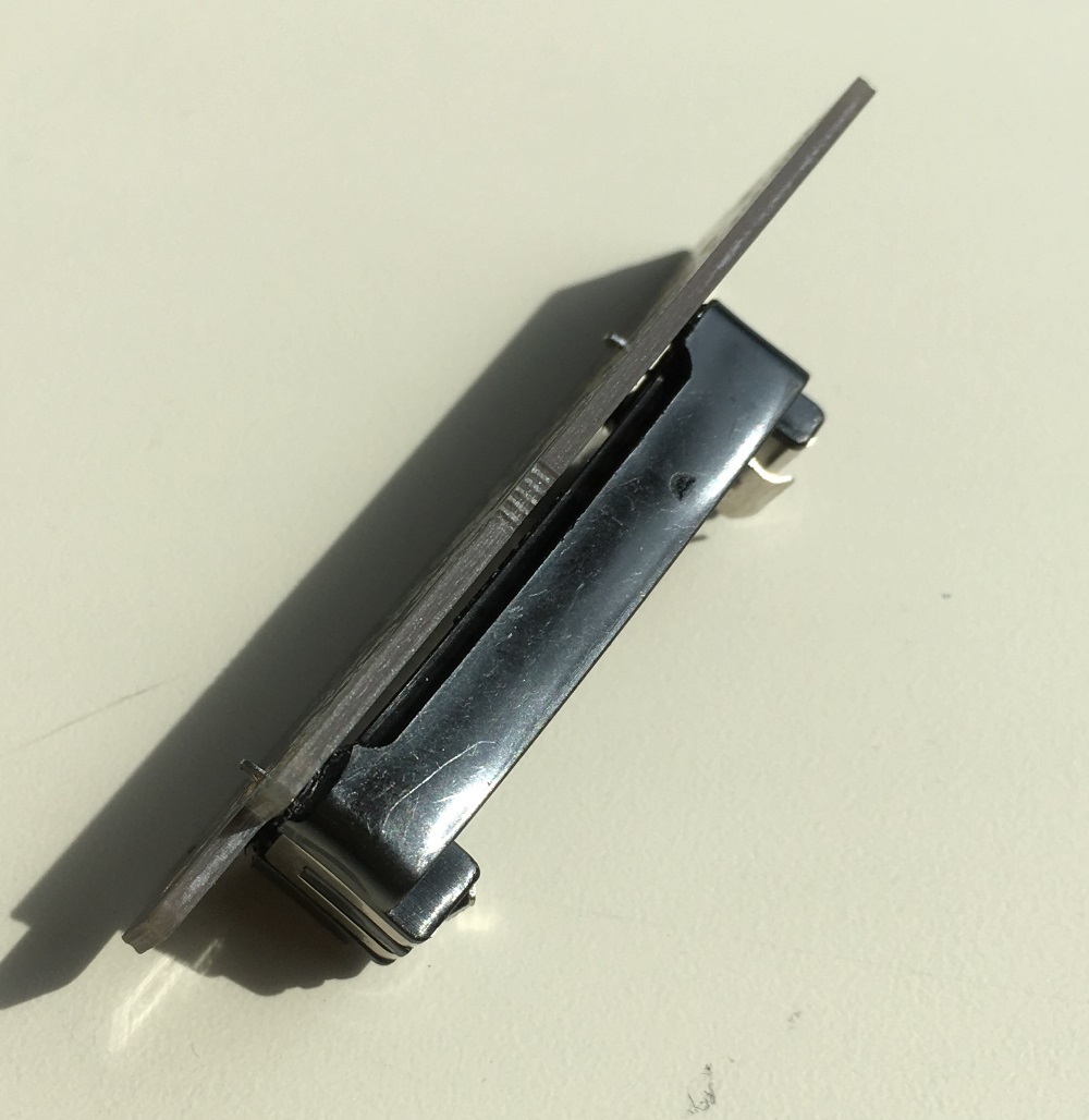
This PCB board can support various battery size and connector such as
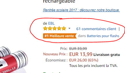
18650

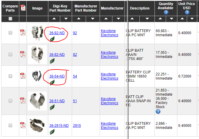
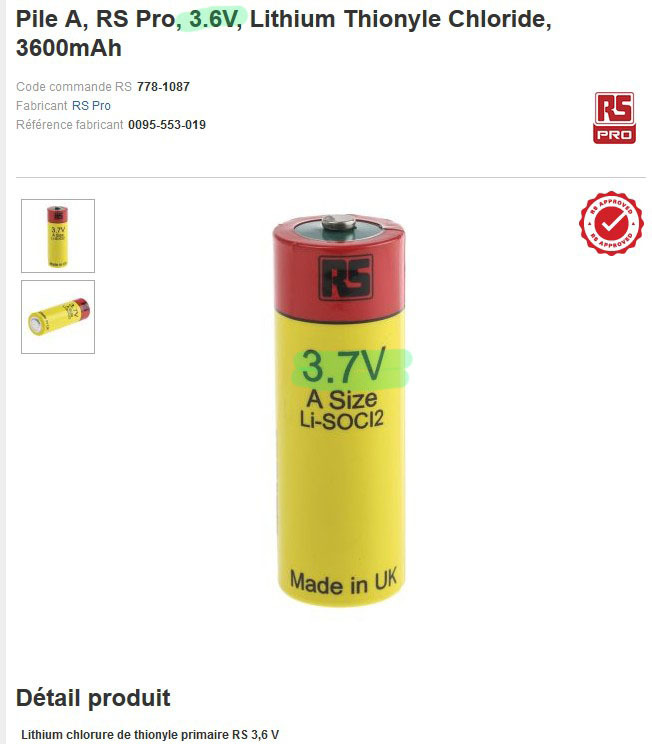
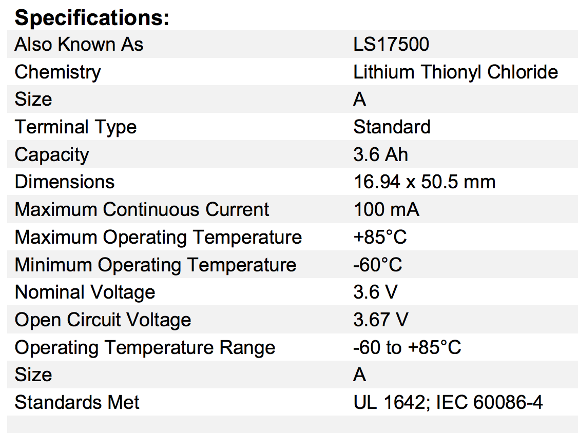
AA (3.6V) with support

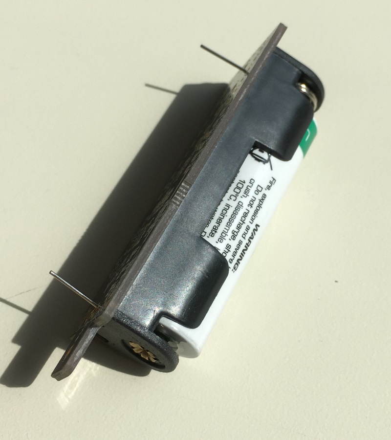
AA (3.6V) with clips
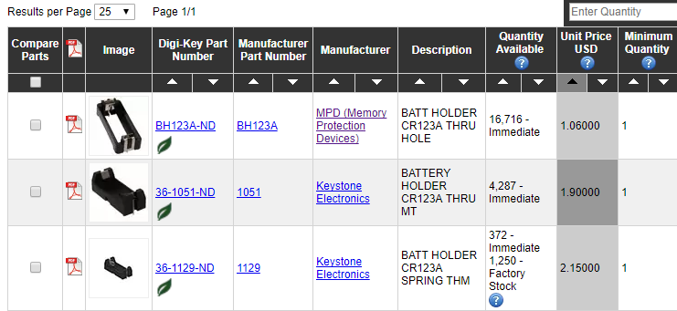
CR123

Schematics can’t be easier

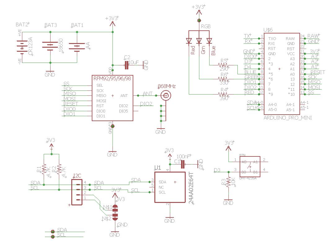
You can order PCB at PCBs.io

And last but not least, this new board should handle sleep mode under 100nA, let me some time to test it, but for now, looks like very promising :wink:

30 Likes

Very nice project! My question is less technical could you please shed the light how do you charge for this R&D to you customer? Do you opt for time&material or is it rather fix-price?

The yellow pcb with the 328p & rfm95w on it, its a special design from yourself? Something like this (an arduino like design but reduced to the minimum necessary) and a bigger atmega (a 1284p for example) would be great to handle more complex stuff (lmic+gps library = not much space left) - thought about a moteino but they are not available in europe and the shipping from them is way off the pricescala.

Btw. love your pcbs - using them for our gateways, would be really cool if there would be a “standard” pcb from you for nodes.

1 Like

That really looks great.

At first I thought : " the batteries are rated 3.7V. Won’t that shorten the expected livespan from the 3.3V parts? Ok 10% isn’t much but magic smoke is allways near. "

But when I check a bunch of 3.3V devices most of them can handle up to 3.7V. Like the RFM95W is rated 2.4 to 3.7V. So safe for that.

Hi Caspar, This one is using a 1284: https://eth0maz.wordpress.com/category/lorawan/

2 Likes

@petekmet
Well, to be honest it really depends on customers and my feeling with them, in this case, it’s more a partnership with him, he provide portal for smart cities and I provide HW for sensors, for now we’re doing demo. But it’s very often fixed price :wink:

@Caspar
The yellow one is just la LoraMini. you can buy it there

Yeah flash size is the deal, I agree, and I love 1284p but man, price is oversized compared to SAMD21. The deal is that I did not had time to investigate on low power capabilities on SAMD and they have no EEP, thus adding external flash is consuming (of course we can simulate EEP with internal flash, but again something to look on). But you know I like to keep things simple, and for basic sensing, this one works like a charm for a price of less than $15, the batterie has the higher cost component… BTW I love moteino, made some custom with I2C pinout for sensors and FTDI under board

@galagaking1
Yeah I love this (old) one, good to know there is a new version, but we can’t built it, no PCB, no schematic, no code nowhere to order and no price. That’s really a pity because this board looks awesome :sweat:

2 Likes

Yet another great little board with accompanying great software from @Charles :+1:

Can you give any recommendations for the battery holders? I guess the pin distances are not always exactly the same? (maybe some nice Aliexpress items for the Bargain Basement?, I won’t ask for Lipo’s because I learned in the meantime not to buy 18650’s from China :confounded:)

How about the question from @lex_ph2lb [quote=“lex_ph2lb, post:4, topic:8059”]
But when I check a bunch of 3.3V devices most of them can handle up to 3.7V. Like the RFM95W is rated 2.4 to 3.7V. So safe for that.
[/quote]

If I’m not mistaken a fully charged Lipo will be at 4.2V, on the other hand: I’ve mistreated RFM95’s several times by accident (5V) and never lost one, so in practice I guess we are safe?

1 Like

Thanks @Batilan
For Battery Holder, I love the clip, easy to test without any soldering, easy to remove battery, love them
For AA/AAA you can find them at mouser/radiospare/digikey for the 18650 (used also for A) it a bit more tricky, I ordered 50 from digikey (keystone)

for CR123 from digikey (MPD) beause it’s the cheaper

For the others PTH with pins, any chineese with long pins should do trick, but some are not headless when you want to remove the battery
yeah I was surprising powering 4.2V RFM95 did not hurt it. SPI speaking, need to check signal strength after and before 5V applied, may be it damaged the radio output.

2 Likes

And for Lipo I did something strange because was faded with my crappy chineese one.
I Went to amazon.fr (test your country) searched and then looked for best commented ones, 61 comments, 5 stars should be not to bad :wink:

Finally took the EBL works great (other tested) and 14€ for 4 is a good deal, received 2 days after, sometimes worth checking near your door instead of “china reflex”

https://www.amazon.fr/gp/product/B06W2GV8ZZ/ref=oh_aui_detailpage_o00_s00?ie=UTF8&psc=1

A bought charger from EBL also, my 25$ one for china was also crappy

1 Like

Thanks! just the info I needed :+1:

Indeed, I also had a look around here in the Netherlands, then NKON seems to stand out, so I’m gonna give them a try (I’m not affiliated with them in any way :innocent:).

another nice board from you. thanks

to be on the save side, why not feeding the battery+ to RAW and taking 3V3 from the Arduino Mini?
Yes, I know 100nA or even 1.3uA would be unattainable

The arduino’s voltage regulator needs in my experience more than 3.7v to work reliable. 4.5v seems to be the lowest acceptable voltage.

@TijnOnlijn if on the Arduino board is really a MIC5205 soldered it should working. It has 150mV drop @ 50mA
I’ve looked precisely at the picture LoraNode-FrontBig, it seems that @Charles has desoldered the LDO

1 Like

All my tested RFM95W worked at least from 2.5V to 5.5V, so they are save to use from a 3.7V LiPo (4.2V full - 2.6V empty), the same worked for the arduino pro minis i tested (3.3V version). Powering them directly from a 6V solar panel did produce resets - so thats not safe. Ergo, there is no need to convert voltages from a standard 3.7V LiPo.

5 Likes

SX1276 has an absolute maximum operating voltage of 3.9V. Recommended operating voltage is 1.8 to 3.7V. From the datasheet: “Stresses above the values listed below may cause permanent device failure. Exposure to absolute maximum ratings for extended periods may affect device reliability”.

3 Likes

Yeah @ursm I desoldered the regulator and cut the trace of the power LED of course. I did not tried with regulator but should be fine to leave it because the power is not going to raw pin but to 3.3V pin.
I use Lipo for testing because it’s cheap and rechargeable but the main goal of the board is to be powered with one of these 3.6V Lithium Thionyle Chloridebattery that are this one 2600mAh or this 3600mAh. Not cheap but I need to place and forget the sensor for years and they are 3.6V so no problem

4 Likes

confusing Charles :wink:

2 Likes

oupss, didn’t noticed this one, need to find my voltmeter friend :wink:

1 Like

Can we order the 2nd board in your post?
Also would you mind sharing the pcb footprint for the lora mini?

1 Like

@ToomanySecrets,
which boards are you talking about ? The one hosting the Lora Mini ?

For now it’s not public and I need to make some improvements after I tested it. May be I will release the code.

The Dragino Lora Mini PCB footprint is available and public, as schematics and board file