Over-the-air-activation OTAA with LMIC

Hi Kibet:disappointed_relieved:,

I am having the same error, I made a lot of changes in my code but is not working at all, the thing here is that I am using a Mini Ultra Pro card with a RFM95W which does not provide DEVEUI address due to this boad (V1) has no EUI-64 chip, so, it reads only zeros, I tried to load a number by my self but still the EV_JOINING is stuck. All I have read since now points out that this number it does not matter too much, and so far my node does not receive anyting at the back end, I only visualize yellow requests in my gateway, which is a mulltichannel Conduit.

Could you please share with me the code you used to make your node work? I have spent two weeks trying to make this to work out without any good result.

Thanks a lot.
Regards.

Hi all,
I’m testing lora node (Arduino UNO + Dragino) with OTAA.

By default the OTAA code use the first 3 lora channels. In some post/code example there was that if you want to use all the 8 lora channels it needs to set the channel in this way:

LMIC_setupChannel(0, 868100000, DR_RANGE_MAP(DR_SF12, DR_SF7), BAND_CENTI); // g-band
LMIC_setupChannel(1, 868300000, DR_RANGE_MAP(DR_SF12, DR_SF7B), BAND_CENTI); // g-band
LMIC_setupChannel(2, 868500000, DR_RANGE_MAP(DR_SF12, DR_SF7), BAND_CENTI); // g-band
LMIC_setupChannel(3, 867100000, DR_RANGE_MAP(DR_SF12, DR_SF7), BAND_CENTI); // g-band
LMIC_setupChannel(4, 867300000, DR_RANGE_MAP(DR_SF12, DR_SF7), BAND_CENTI); // g-band
LMIC_setupChannel(5, 867500000, DR_RANGE_MAP(DR_SF12, DR_SF7), BAND_CENTI); // g-band
LMIC_setupChannel(6, 867700000, DR_RANGE_MAP(DR_SF12, DR_SF7), BAND_CENTI); // g-band
LMIC_setupChannel(7, 867900000, DR_RANGE_MAP(DR_SF12, DR_SF7), BAND_CENTI); // g-band
LMIC_setupChannel(8, 868800000, DR_RANGE_MAP(DR_FSK, DR_FSK), BAND_MILLI); // g2-band

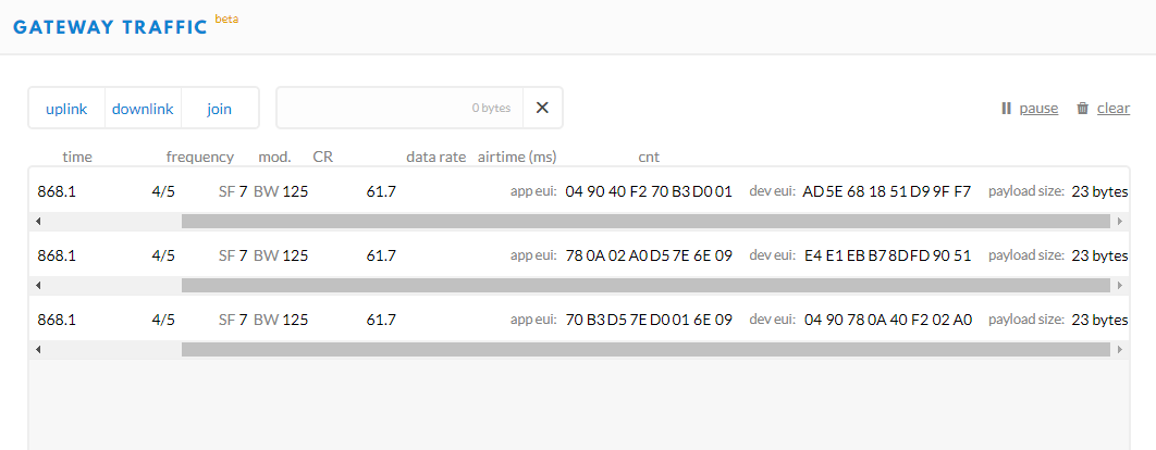
I tryed but both on the lora server side and on the gateway I can see that the node uses only 3 channels (the default channels 0,1,2).

Thanks in advance for your help!!
Following the code that I use:

/*******************************************************************************
Original script is Copyright (c) 2015 Thomas Telkamp and Matthijs Kooijman
 *******************************************************************************/

#include <lmic.h>
#include <hal/hal.h>
#include <SPI.h>

static const u1_t APPEUI[8]  = { 0x04, 0x00, 0x00, 0x00, 0x00, 0x00, 0x00, 0x00 }; // REVERSE ORDER
static const u1_t DEVEUI[8]  = { 0x04, 0x00, 0x00, 0x00, 0x00, 0x00, 0x00, 0x00 }; // REVERSE ORDER
static const u1_t APPKEY[16] = { 0x01, 0x00, 0x00, 0x00, 0x00, 0x00, 0x00, 0x00, 0x00, 0x00, 0x00, 0x00, 0x00, 0x00, 0x00, 0x01 };

// provide APPEUI (8 bytes, LSBF)
void os_getArtEui (u1_t* buf) {
  memcpy(buf, APPEUI, 8);
}

// provide DEVEUI (8 bytes, LSBF)
void os_getDevEui (u1_t* buf) {
  memcpy(buf, DEVEUI, 8);
}

// provide APPKEY key (16 bytes)
void os_getDevKey (u1_t* buf) {
  memcpy(buf, APPKEY, 16);
}

static uint8_t mydata[] = "Hello, TTN over OTAA!";
static osjob_t sendjob;
static osjob_t initjob;

// Schedule TX every this many seconds (might become longer due to duty
// cycle limitations).
const unsigned TX_INTERVAL = 5;

// Pin mapping
const lmic_pinmap lmic_pins = {
  .nss = 10,
  .rxtx = LMIC_UNUSED_PIN,
  .rst = 9,
  .dio = {2, 6, 7},
};

void onEvent (ev_t ev) {
  Serial.print(os_getTime());
  Serial.print(": ");
  switch (ev) {
    case EV_SCAN_TIMEOUT:
      Serial.println(F("EV_SCAN_TIMEOUT"));
      break;
    case EV_BEACON_FOUND:
      Serial.println(F("EV_BEACON_FOUND"));
      break;
    case EV_BEACON_MISSED:
      Serial.println(F("EV_BEACON_MISSED"));
      break;
    case EV_BEACON_TRACKED:
      Serial.println(F("EV_BEACON_TRACKED"));
      break;
    case EV_JOINING: 
      Serial.println(F("EV_JOINING"));
      break;
    case EV_JOINED:
      Serial.println(F("EV_JOINED"));
      do_send(&sendjob);
      break;
    case EV_RFU1:
      Serial.println(F("EV_RFU1"));
      break;
    case EV_JOIN_FAILED:
      Serial.println(F("EV_JOIN_FAILED"));
      break;
    case EV_REJOIN_FAILED:
      Serial.println(F("EV_REJOIN_FAILED"));
      // Re-init
      os_setCallback(&initjob, initfunc);      
      break;
    case EV_TXCOMPLETE:
      Serial.println(F("EV_TXCOMPLETE (includes waiting for RX windows)"));
      if (LMIC.dataLen) {
        // data received in rx slot after tx
        Serial.print(F("Data Received: "));
        //Serial.write(LMIC.frame + LMIC.dataBeg, LMIC.dataLen);
        Serial.println();
      }
      // Schedule next transmission
      os_setTimedCallback(&sendjob, os_getTime() + sec2osticks(TX_INTERVAL), do_send);
      break;
    case EV_LOST_TSYNC:
      Serial.println(F("EV_LOST_TSYNC"));
      break;
    case EV_RESET:
      Serial.println(F("EV_RESET"));
      break;
    case EV_RXCOMPLETE:
      // data received in ping slot
      Serial.println(F("EV_RXCOMPLETE"));
      break;
    case EV_LINK_DEAD:
      Serial.println(F("EV_LINK_DEAD"));
      break;
    case EV_LINK_ALIVE:
      Serial.println(F("EV_LINK_ALIVE"));
      break;
    default:
      Serial.println(F("Unknown event"));
      break;
  }
}

void do_send(osjob_t* j) {
  // Check if there is not a current TX/RX job running
  if (LMIC.opmode & OP_TXRXPEND) {
    Serial.println(F("OP_TXRXPEND, not sending"));
  } else {
    // Prepare upstream data transmission at the next possible time.
    LMIC_setTxData2(1, mydata, sizeof(mydata) - 1, 0);
    Serial.println(F("Packet queued"));
  }
}

// initial job
static void initfunc (osjob_t* j) {
    // reset MAC state
    LMIC_reset();
    // start joining
    LMIC_startJoining();
    // init done - onEvent() callback will be invoked...
}

void setup() {
  Serial.begin(115200);
  Serial.println(F("Starting"));
  // LMIC init
  os_init();
  // Reset the MAC state. Session and pending data transfers will be discarded.
  os_setCallback(&initjob, initfunc);

  LMIC_setClockError(MAX_CLOCK_ERROR * 1 / 100);

  // Set up the channels used by the Things Network, which corresponds
  // to the defaults of most gateways. Without this, only three base
  // channels from the LoRaWAN specification are used, which certainly
  // works, so it is good for debugging, but can overload those
  // frequencies, so be sure to configure the full frequency range of
  // your network here (unless your network autoconfigures them).
  // Setting up channels should happen after LMIC_setSession, as that
  // configures the minimal channel set.
  
  LMIC_setupChannel(0, 868100000, DR_RANGE_MAP(DR_SF12, DR_SF7),  BAND_CENTI);      // g-band
  LMIC_setupChannel(1, 868300000, DR_RANGE_MAP(DR_SF12, DR_SF7B), BAND_CENTI);      // g-band
  LMIC_setupChannel(2, 868500000, DR_RANGE_MAP(DR_SF12, DR_SF7),  BAND_CENTI);      // g-band
  LMIC_setupChannel(3, 867100000, DR_RANGE_MAP(DR_SF12, DR_SF7),  BAND_CENTI);      // g-band
  LMIC_setupChannel(4, 867300000, DR_RANGE_MAP(DR_SF12, DR_SF7),  BAND_CENTI);      // g-band
  LMIC_setupChannel(5, 867500000, DR_RANGE_MAP(DR_SF12, DR_SF7),  BAND_CENTI);      // g-band
  LMIC_setupChannel(6, 867700000, DR_RANGE_MAP(DR_SF12, DR_SF7),  BAND_CENTI);      // g-band
  LMIC_setupChannel(7, 867900000, DR_RANGE_MAP(DR_SF12, DR_SF7),  BAND_CENTI);      // g-band
  LMIC_setupChannel(8, 868800000, DR_RANGE_MAP(DR_FSK,  DR_FSK),  BAND_MILLI);      // g2-band
  // TTN defines an additional channel at 869.525Mhz using SF9 for class B
  // devices' ping slots. LMIC does not have an easy way to define set this
  // frequency and support for class B is spotty and untested, so this
  // frequency is not configured here.

  // Disable link check validation
  LMIC_setLinkCheckMode(0);

  // required for downlink
  LMIC.dn2Dr = SF9;

  // Set data rate and transmit power (note: txpow seems to be ignored by the library)
  LMIC_setDrTxpow(DR_SF7, 14);

  os_runloop();
  // Never get here
}

void loop() {
  // Never get here
}

please FORMAT your forum post… especially the loooooooooooooong copy/pasted code :roll_eyes:

Ok done!
waiting for some help…

1 Like

what exactly is your gateway (dragino + rpi ?)

It is a rpi3 with LoRa concentrator like this one https://www.thethingsnetwork.org/labs/story/how-to-build-your-own-lorawan-gateway
Moreover I tested this lora server: Alternative LoRaWAN network-server: loraserver.io (with packet forwarder and gateway bridge).

It works well with ABP, if I set all the 8 channels, the node uses all the 8 channels. OTAA works well the only point is that I would like to use all the 8 lora channels also with OTAA, not only the first 3 channels

Thx

I tested some time ago also it on TTN and I got the same outcome.

this is the TTN forum so for support on the Brocaar loraserver better to ask there

maybe there are here some topics off interest
.

Hello all,

My first message here, not sure if this is the right place. Nevertheless:

I have an Adafruit feather M0 and followed various online manuals (mainly https://community.hiveeyes.org/t/using-the-adafruit-feather-m0-lora-rfm95-and-ttn/528) to adapt and load the ttn-otaa sketch. By accident in the sketch I copied a DevEUI that I previously registered with a TTN Uno board and messages came through marvelously.

Then I registered a new device, had ttn generate a DevEUI and put that in the sketch (with the byte order reversed as I did before). I uploaded the sketch and … nothing.

Reverting again to the previous DevEUI in my sketch, it immediately worked again. Very reproducible.

Does anyone have an idea what I might have overlooked? Why doesn’t it work with a newly generated and registered DevEUI?

Thanks!

Wouter.

first thought : the TTN uno board doesn’t use LMIC while the Adafruit feather does.
So these should be 2 totally different sketches … not only the keys.

Thanks for the thought.

Indeed. I used entirely different code on the TTN Uno and the Feather M0. In the sketch for the Feather M0 I got messages through to my ttn console if I used the DevEUI that I previously used for the Uno. If I then only change the DevEUI in that sketch (a new one generated by TTN), it doesn’t work.

In the TTN Uno DevEUI is determined by the manufacturer. Do I understand correctly that for the LMIC route with an RFM95 it is not and it needs to be assigned in the sketch? If so, why does one DevEUI work (the one I accidentally copied from an entirely different node) and another (generated by ttn) does not?

you copied the key to the new lmic device… TTN thinks it still the first device you registered , with TTN UNO the keys are in the main module the rn2483, so if you use the generated key for that node and add it to a sketch for another TTN uno it won’t work.

Understood. This helps me understand a little bit better.

So, because of re-using the DevEUI of the Uno, TTN thinks I am still using that TTN UNO node, whereas I am actually using the feather M0. Since TTN receives the messages, this at least tells me that all the Feather hard- and software works.

What is puzzling me is when I then (i) register a new device on TTN in the same application, (ii) have TTN generate a new DevEUI, (iii) change only the DevEUI in the sketch, and (iv) upload the sketch to the feather, I don’t see any messages coming on on the TTN console for that application.

https://www.thethingsnetwork.org/docs/devices/

Ah, thank you. So the TTN generate button is for ABP only! Does the feather/RFN95 have an hardware defined DevEUI and how do I find out about it? Guess I have some more reading/understanding to do.

1 Like

or use search here on the site

When you register a new device the APP key will be different, did you update both the EUI to the generated value and the App key?

I never thought of the App key being different (assuming, wrongly so, that it registers to the same application). Will give it a try. Thank you!

… SOLVED … Many thanks!

Hello! I have a custom single channel LoRa Gateway and I started with ABP which worked fine. Now I am trying the OTAA and although I can see the first packet both on my gateway console

Packet RSSI: -67, RSSI: -94, SNR: 9, Length: 23
rxpk update: {“rxpk”:[{“tmst”:4046223465,“chan”:0,“rfch”:0,“freq”:868.100000,“stat”:1,“modu”:“LORA”,“datr”:“SF7BW125”,“codr”:“4/5”,“lsnr”:9,“rssi”:-67,“size”:23,“data”:“AAluftWgAgp4UZD9jbfr4eSA77r9ZZs=”}]}

and on the TTN gateway console

{
  "gw_id": "eui-b827ebffff0292e1",
  "payload": "AAHQs3DyQJAE95/ZURhoXq2/oqb2UMM=",
  "dev_eui": "AD5E681851D99FF7",
  "lora": {
    "spreading_factor": 7,
    "bandwidth": 125,
    "air_time": 61696000
  },
  "coding_rate": "4/5",
  "timestamp": "2019-01-23T18:05:42.068Z",
  "rssi": -67,
  "snr": 9,
  "app_eui": "049040F270B3D001",
  "frequency": 868100000
}

But I don’t see the rest of the process to continue. In example the Serial monitor repeats this state EV_TXSTART

20:05:34.479 -> Starting
20:05:34.547 -> Packet queued
20:05:34.547 -> 196: EV_JOINING
20:05:41.512 -> 438616: EV_TXSTART
20:06:50.618 -> 4768566: EV_TXSTART
20:07:57.008 -> 8927362: EV_TXSTART
...

I have copy pasted very carefully the OTAA credentials to the sketch.
Also I have made these configurations to “agree” with EU frequencies and the Arduino Uno as “Mobilefish” suggests

// project-specific definitions
//#define CFG_eu868 1
#define CFG_eu868 1
//#define CFG_au921 1
//#define CFG_as923 1
// #define LMIC_COUNTRY_CODE LMIC_COUNTRY_CODE_JP /* for as923-JP */
//#define CFG_in866 1
#define CFG_sx1276_radio 1
//#define LMIC_USE_INTERRUPTS
#define DISABLE_PING
#define DISABLE_BEACONS
#define LMIC_DEBUG_LEVEL 0
#define USE_IDEETRON_AES

Also, how the different app eui and dev eui accross three continuous messages is explained?


Anyway, no matter my efforts I still have not achieved a OTAA connection, if anyone could help me that would be great. Thank you!

Single channel gateways are not LoRaWAN specs conform. You can’t use a single channel gateway for OTA.