No Problem, but remember, i write it only for first test and used much from Arduino-lmic example, so very dirty.
And i only use a single channel gateway, so if you use a full GW, you must uncomment the block with “LMIC_setupChannel” and delete my definitions!
Good luck & if you have any questions, contact me!
/*******************************************************************************
Copyright (c) 2015 Thomas Telkamp and Matthijs Kooijman
Permission is hereby granted, free of charge, to anyone
obtaining a copy of this document and accompanying files,
to do whatever they want with them without any restriction,
including, but not limited to, copying, modification and redistribution.
NO WARRANTY OF ANY KIND IS PROVIDED.
This example sends a valid LoRaWAN packet with payload "Hello,
world!", using frequency and encryption settings matching those of
the The Things Network.
This uses ABP (Activation-by-personalisation), where a DevAddr and
Session keys are preconfigured (unlike OTAA, where a DevEUI and
application key is configured, while the DevAddr and session keys are
assigned/generated in the over-the-air-activation procedure).
Note: LoRaWAN per sub-band duty-cycle limitation is enforced (1% in
g1, 0.1% in g2), but not the TTN fair usage policy (which is probably
violated by this sketch when left running for longer)!
To use this sketch, first register your application and device with
the things network, to set or generate a DevAddr, NwkSKey and
AppSKey. Each device should have their own unique values for these
fields.
Do not forget to define the radio type correctly in config.h.
*******************************************************************************/
#include <Arduino.h>
#include <U8g2lib.h>
#include <lmic.h>
#include <hal/hal.h>
#include <SPI.h>
#include <Wire.h>
// Enable debug prints to serial monitor
#define MY_DEBUG
int BATTERY_SENSE_PIN = A0;
int BATTERY_FULL = 4.2;
U8G2_SSD1306_128X32_UNIVISION_F_HW_I2C u8g2(U8G2_R0, /* reset=*/ U8X8_PIN_NONE, /* clock=*/ SCL, /* data=*/ SDA); // pin remapping with ESP8266 HW I2C
// LoRaWAN NwkSKey, network session key
// This is the default Semtech key, which is used by the early prototype TTN
// network.
// DEVEUI und AppEUI **LSB**
static const PROGMEM u1_t NWKSKEY[16] = { 0xAA ....};
// LoRaWAN AppSKey, application session key
// This is the default Semtech key, which is used by the early prototype TTN
// network.
// **MSB**
static const u1_t PROGMEM APPSKEY[16] = { 0xAA ....};
// LoRaWAN end-device address (DevAddr) Write 0x and than the DevADD as Numbers
static const u4_t DEVADDR = 0x0123456789;
// These callbacks are only used in over-the-air activation, so they are
// left empty here (we cannot leave them out completely unless
// DISABLE_JOIN is set in config.h, otherwise the linker will complain).
void os_getArtEui (u1_t* buf) { }
void os_getDevEui (u1_t* buf) { }
void os_getDevKey (u1_t* buf) { }
static uint8_t mydata[] = "Hello, world!";
static osjob_t sendjob;
// Schedule TX every this many seconds (might become longer due to duty
// cycle limitations).
const unsigned TX_INTERVAL = 60;
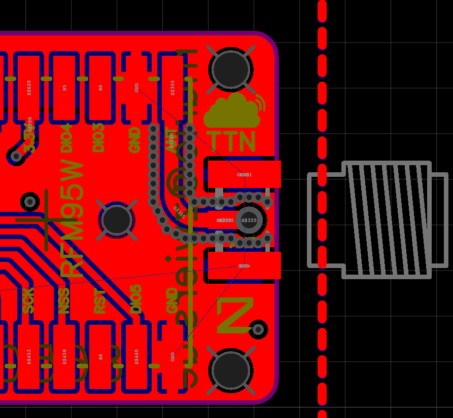
// Pin mapping for Marioz PCB
const lmic_pinmap lmic_pins = {
.nss = 10,
.rxtx = LMIC_UNUSED_PIN,
.rst = 9,
.dio = {4, 5, 7}, //DIO0, DIO1 and DIO2 connected
};
void onEvent (ev_t ev) {
Serial.print(os_getTime());
Serial.print(": ");
switch (ev) {
case EV_SCAN_TIMEOUT:
Serial.println(F("EV_SCAN_TIMEOUT"));
break;
case EV_BEACON_FOUND:
Serial.println(F("EV_BEACON_FOUND"));
break;
case EV_BEACON_MISSED:
Serial.println(F("EV_BEACON_MISSED"));
break;
case EV_BEACON_TRACKED:
Serial.println(F("EV_BEACON_TRACKED"));
break;
case EV_JOINING:
Serial.println(F("EV_JOINING"));
break;
case EV_JOINED:
Serial.println(F("EV_JOINED"));
break;
case EV_RFU1:
Serial.println(F("EV_RFU1"));
break;
case EV_JOIN_FAILED:
Serial.println(F("EV_JOIN_FAILED"));
break;
case EV_REJOIN_FAILED:
Serial.println(F("EV_REJOIN_FAILED"));
break;
case EV_TXCOMPLETE:
Serial.println(F("EV_TXCOMPLETE (includes waiting for RX windows)"));
if (LMIC.txrxFlags & TXRX_ACK)
Serial.println(F("Received ack"));
if (LMIC.dataLen) {
Serial.println(F("Received "));
Serial.print(LMIC.dataLen);
Serial.println(F(" bytes of payload"));
}
// Schedule next transmission
os_setTimedCallback(&sendjob, os_getTime() + sec2osticks(TX_INTERVAL), do_send);
break;
case EV_LOST_TSYNC:
Serial.println(F("EV_LOST_TSYNC"));
break;
case EV_RESET:
Serial.println(F("EV_RESET"));
break;
case EV_RXCOMPLETE:
// data received in ping slot
Serial.println(F("EV_RXCOMPLETE"));
break;
case EV_LINK_DEAD:
Serial.println(F("EV_LINK_DEAD"));
break;
case EV_LINK_ALIVE:
Serial.println(F("EV_LINK_ALIVE"));
break;
default:
Serial.println(F("Unknown event"));
break;
}
}
void do_send(osjob_t* j) {
// Read sensor values and multiply by 100 to effectively keep 2 decimals
// Signed 16 bits integer, -32767 up to +32767
int16_t t = 0;
// Unsigned 16 bits integer, 0 up to 65535
uint16_t h = 0;
// Unsigned 16 bits integer, 0 up to 65535
uint16_t b = readBat() * 100;
byte buffer[6];
buffer[0] = t >> 8;
buffer[1] = t;
buffer[2] = h >> 8;
buffer[3] = h;
buffer[4] = b >> 8;
buffer[5] = b;
LMIC_setTxData2(1, buffer, sizeof(buffer), 0);
Serial.println("");
Serial.print("Sending - temperature: ");
Serial.print(t);
Serial.print(", humidity: ");
Serial.print(h);
Serial.print(", battery: ");
Serial.print(b);
Serial.println("");
// Check if there is not a current TX/RX job running
if (LMIC.opmode & OP_TXRXPEND) {
Serial.println(F("OP_TXRXPEND, not sending"));
} else {
// Prepare upstream data transmission at the next possible time.
LMIC_setTxData2(1, buffer, sizeof(buffer), 0);
Serial.println(F("Packet queued"));
}
// Next TX is scheduled after TX_COMPLETE event.
}
void setup() {
Serial.begin(115200);
Serial.println(F("Starting"));
// Fuer A0 Battery:
analogReference(INTERNAL);
#ifdef VCC_ENABLE
// For Pinoccio Scout boards
pinMode(VCC_ENABLE, OUTPUT);
digitalWrite(VCC_ENABLE, HIGH);
delay(1000);
#endif
// LMIC init
os_init();
// Reset the MAC state. Session and pending data transfers will be discarded.
LMIC_reset();
// Set static session parameters. Instead of dynamically establishing a session
// by joining the network, precomputed session parameters are be provided.
#ifdef PROGMEM
// On AVR, these values are stored in flash and only copied to RAM
// once. Copy them to a temporary buffer here, LMIC_setSession will
// copy them into a buffer of its own again.
uint8_t appskey[sizeof(APPSKEY)];
uint8_t nwkskey[sizeof(NWKSKEY)];
memcpy_P(appskey, APPSKEY, sizeof(APPSKEY));
memcpy_P(nwkskey, NWKSKEY, sizeof(NWKSKEY));
LMIC_setSession (0x1, DEVADDR, nwkskey, appskey);
#else
// If not running an AVR with PROGMEM, just use the arrays directly
LMIC_setSession (0x1, DEVADDR, NWKSKEY, APPSKEY);
#endif
#if defined(CFG_eu868)
// Set up the channels used by the Things Network, which corresponds
// to the defaults of most gateways. Without this, only three base
// channels from the LoRaWAN specification are used, which certainly
// works, so it is good for debugging, but can overload those
// frequencies, so be sure to configure the full frequency range of
// your network here (unless your network autoconfigures them).
// Setting up channels should happen after LMIC_setSession, as that
// configures the minimal channel set.
// NA-US channels 0-71 are configured automatically
// LMIC_setupChannel(0, 868100000, DR_RANGE_MAP(DR_SF12, DR_SF7), BAND_CENTI); // g-band
// LMIC_setupChannel(1, 868300000, DR_RANGE_MAP(DR_SF12, DR_SF7B), BAND_CENTI); // g-band
// LMIC_setupChannel(2, 868500000, DR_RANGE_MAP(DR_SF12, DR_SF7), BAND_CENTI); // g-band
// LMIC_setupChannel(3, 867100000, DR_RANGE_MAP(DR_SF12, DR_SF7), BAND_CENTI); // g-band
// LMIC_setupChannel(4, 867300000, DR_RANGE_MAP(DR_SF12, DR_SF7), BAND_CENTI); // g-band
// LMIC_setupChannel(5, 867500000, DR_RANGE_MAP(DR_SF12, DR_SF7), BAND_CENTI); // g-band
// LMIC_setupChannel(6, 867700000, DR_RANGE_MAP(DR_SF12, DR_SF7), BAND_CENTI); // g-band
// LMIC_setupChannel(7, 867900000, DR_RANGE_MAP(DR_SF12, DR_SF7), BAND_CENTI); // g-band
// LMIC_setupChannel(8, 868800000, DR_RANGE_MAP(DR_FSK, DR_FSK), BAND_MILLI); // g2-band
LMIC_setupChannel(0, 868100000, DR_RANGE_MAP(DR_SF12, DR_SF7), BAND_CENTI); // g-band
LMIC_setupChannel(1, 868100000, DR_RANGE_MAP(DR_SF12, DR_SF7B), BAND_CENTI); // g-band
LMIC_setupChannel(2, 868100000, DR_RANGE_MAP(DR_SF12, DR_SF7), BAND_CENTI); // g-band
LMIC_setupChannel(3, 868100000, DR_RANGE_MAP(DR_SF12, DR_SF7), BAND_CENTI); // g-band
LMIC_setupChannel(4, 868100000, DR_RANGE_MAP(DR_SF12, DR_SF7), BAND_CENTI); // g-band
LMIC_setupChannel(5, 868100000, DR_RANGE_MAP(DR_SF12, DR_SF7), BAND_CENTI); // g-band
LMIC_setupChannel(6, 868100000, DR_RANGE_MAP(DR_SF12, DR_SF7), BAND_CENTI); // g-band
LMIC_setupChannel(7, 868100000, DR_RANGE_MAP(DR_SF12, DR_SF7), BAND_CENTI); // g-band
LMIC_setupChannel(8, 868100000, DR_RANGE_MAP(DR_FSK, DR_FSK), BAND_MILLI); // g2-
// TTN defines an additional channel at 869.525Mhz using SF9 for class B
// devices' ping slots. LMIC does not have an easy way to define set this
// frequency and support for class B is spotty and untested, so this
// frequency is not configured here.
#elif defined(CFG_us915)
// NA-US channels 0-71 are configured automatically
// but only one group of 8 should (a subband) should be active
// TTN recommends the second sub band, 1 in a zero based count.
// https://github.com/TheThingsNetwork/gateway-conf/blob/master/US-global_conf.json
LMIC_selectSubBand(1);
#endif
// Disable link check validation
LMIC_setLinkCheckMode(0);
// TTN uses SF9 for its RX2 window.
LMIC.dn2Dr = DR_SF9;
// Set data rate and transmit power for uplink (note: txpow seems to be ignored by the library)
LMIC_setDrTxpow(DR_SF7, 14);
// Start job
do_send(&sendjob);
}
float readBat() {
int sensorValue = analogRead(BATTERY_SENSE_PIN);
#ifdef MY_DEBUG
Serial.println(sensorValue);
#endif
// 2M, 470K divider across battery and using internal ADC ref of 1.1V
// Sense point is bypassed with 0.1 uF cap to reduce noise at that point
// ((2e6+470e3)/470e3)*1.1 = Vmax = 5,78 Volts
// 5,78/1023 = Volts per bit = 0.00565
#ifdef MY_DEBUG
float batteryV = sensorValue * 0.00565;
Serial.print("Battery Voltage: ");
Serial.print(batteryV);
Serial.println(" V");
#endif
return batteryV;
}
void loop() {
os_runloop_once();
}
 )
)


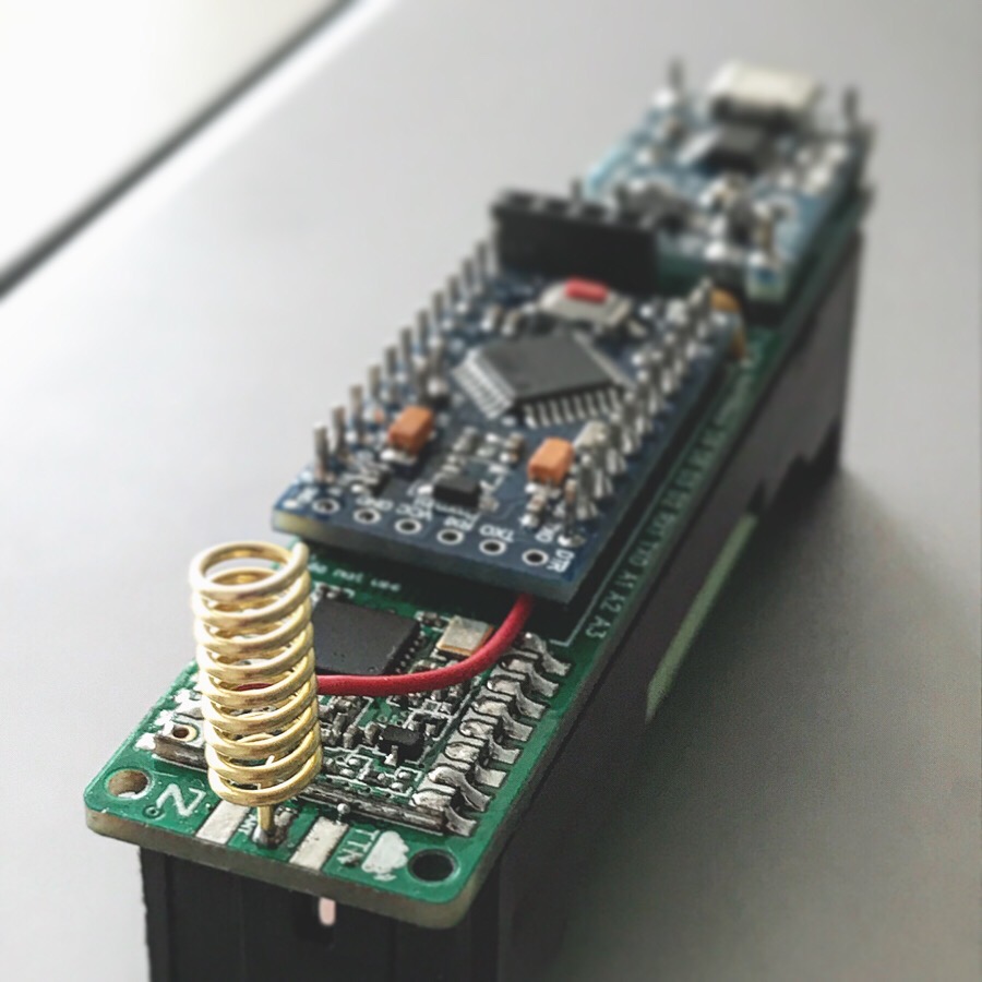
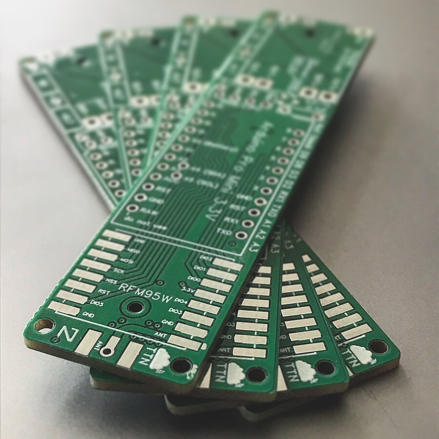
 I like this concept very much…