Hello.
I am from México. I need your help to fix my gateways.
I have five TTN 915 MHz Gateway´s running firmware v1.0.5. They are in different sites of my city.
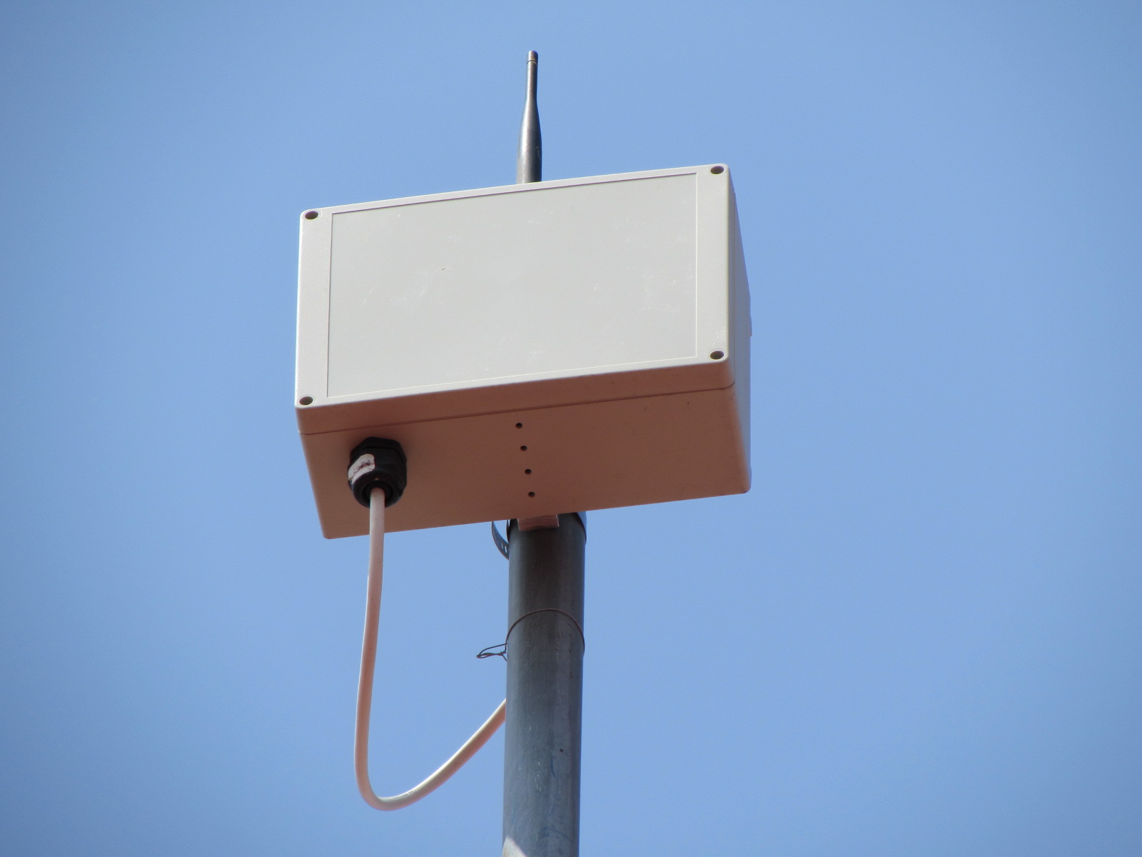
To increase the GW range, I put outside two of them, with the next installations:
- TTN GWs into an IP65 ABS box placed on the top of a 6m metal pole.
- Original GW antenna.
- Power over an 8m STP Cat5e Ethernet cable with the TP-LINK TL-POE200 Kit.
- The PoE kit is supply by a 127 VCA 90 J surge suppressor.
- A TP-LINK TL-WA855RE Wi-Fi range extender isolates the GW from the Internet home router.
- No ground system.
Next the installation, the GWs range was about 2 km with RSSI around -70 from fixed nodes.
After a rain with nearby lightning strike, the GWs range dropped to about 100m with RSSI around -105 from fixed nodes.
I changed the GW installation to an internal place to avoid more damage. They didn’t recovery their original range an RSSI values.
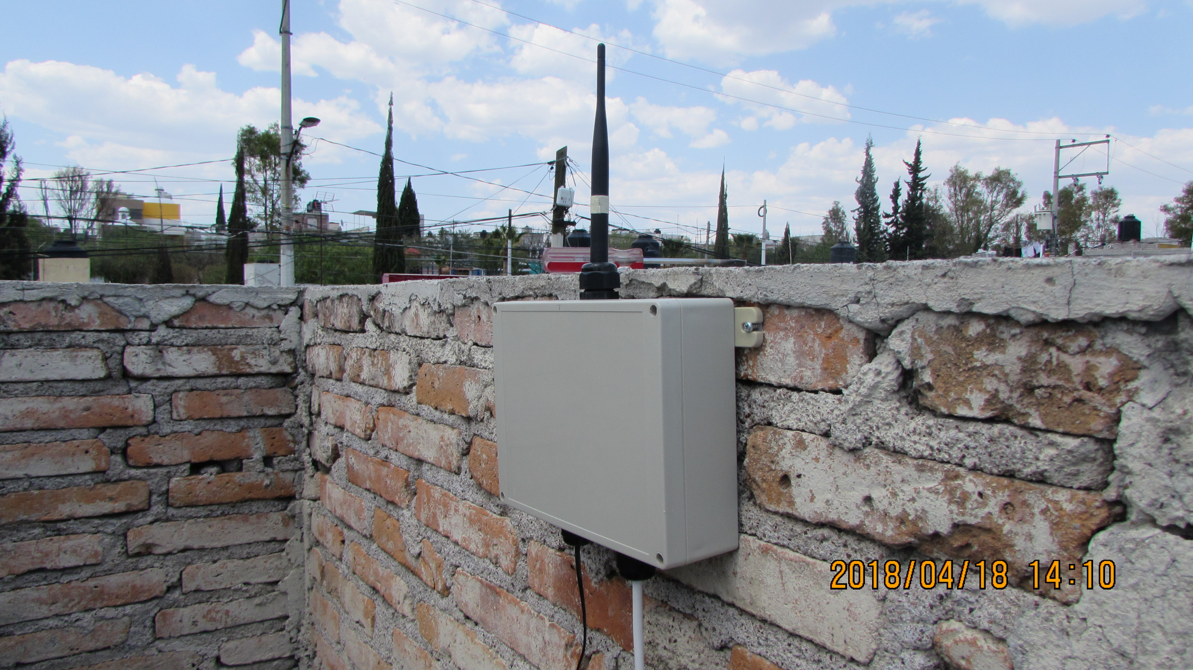
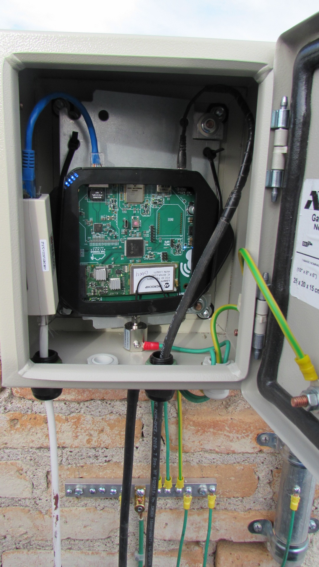
I installed another TTN GW outside. I tried to protect it at the most:
- TTN GW into an IP65 metal box placed on the roof of a house.
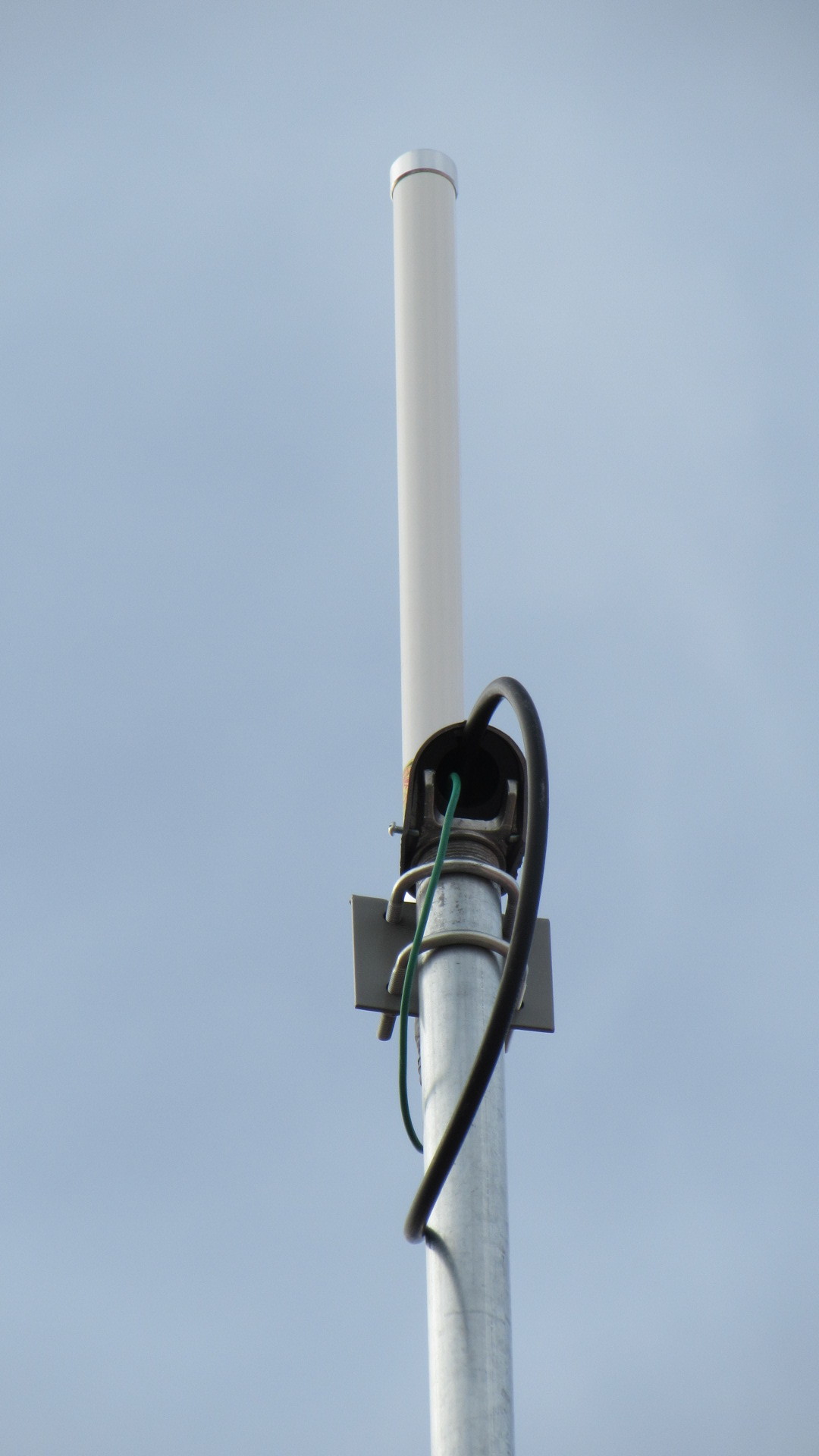
- 824-960 MHz 6 dBi Omni antenna from Altelix, mounted on the top of a 5m metal pole over the roof.
- A 20ft RPSMA M / N M 400FR-Series coaxial cable between the antenna and the GW.
- Antenna lightning protection: N-Male to N-Female Bulkhead 0-6.4 GHz Gas Tube Lightning Protector with a 600V gas tube.
- GW lightning protection: RP-SMA Male to RP-SMA Female Bulkhead RFID & WiFi Lightning Protector 0-6.4 GHz with a 90V gas tube.
- Ethernet cable surge protector: TRIPP-LITE SUPRESOR RJ45 (DNET1).
- Home Internet router protection: A TP-LINK TL-WA855RE Wi-Fi range extender isolates the GW from the Internet home router.
- Supply protection: TTN GW AC adapter protected with a 127 VAC surge suppressor (90 J).
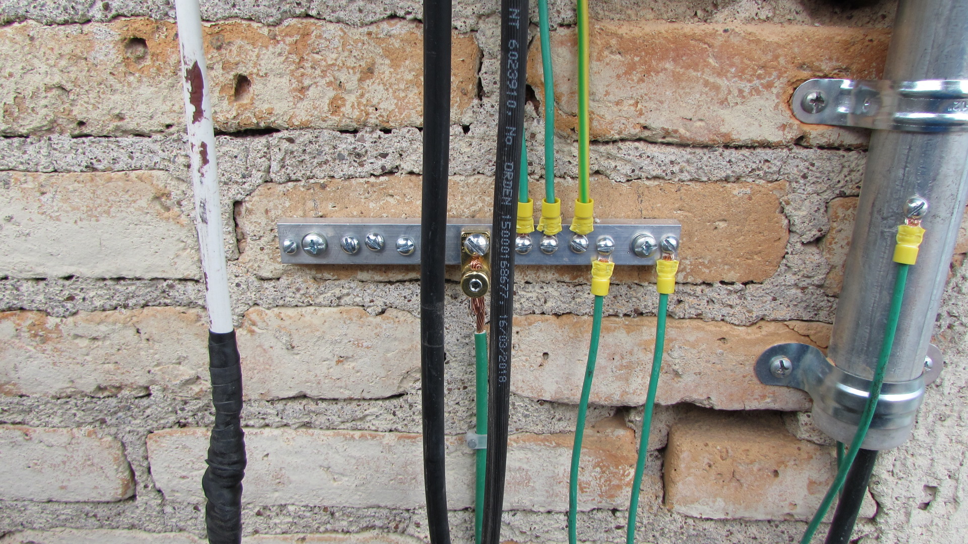
- Ground system:
- Earth electrode: three conductive interconnected rods driven into the ground.
- 20m 8 AWG cable from the rods to an aluminum bar near the GW.
- Single point ground near the GW (aluminum bar).
- Metal pole, GW metal box, RJ45 suppressor, lightning protectors and Ethernet cable directly connected to the single point ground.
This TTN GW resisted the first rain, but with the next storm, the RSSI dropped to around -105. After the last storm, the RSSI changed to around -125 with a 20m maximum range.
I want to fix my TTN GWs.
The public documentation I have is the TTN GW schematic diagram (ttn_gateway_V2.3.1.pdf file) from:
https://github.com/TheThingsProducts/gateway/blob/develop/hardware/TTN_Gateway_V2.3.1.pdf
the Microchip GW schematic diagram at the LoRa Technology Gateway User’s Guide (40001827A.pdf file) from:
and the Semtech PicoCell Gateway V1.0 Prod Folder for North America reference design schematic diagram (SX1308P915GW_Picocell_GTW_e381v02c_sch.pdf file) from:
https://www.semtech.com/products/wireless-rf/lora-gateways/SX1308
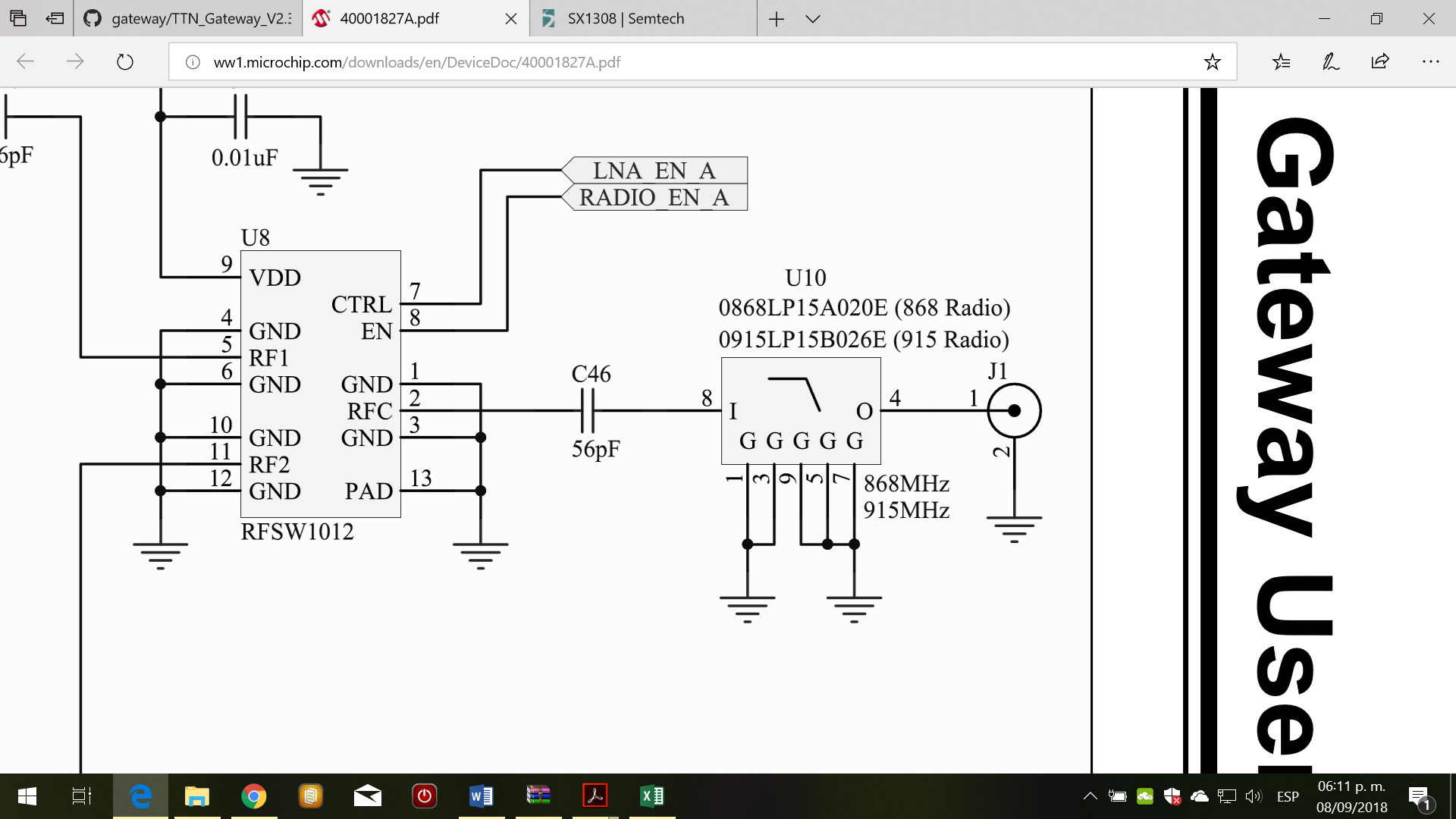
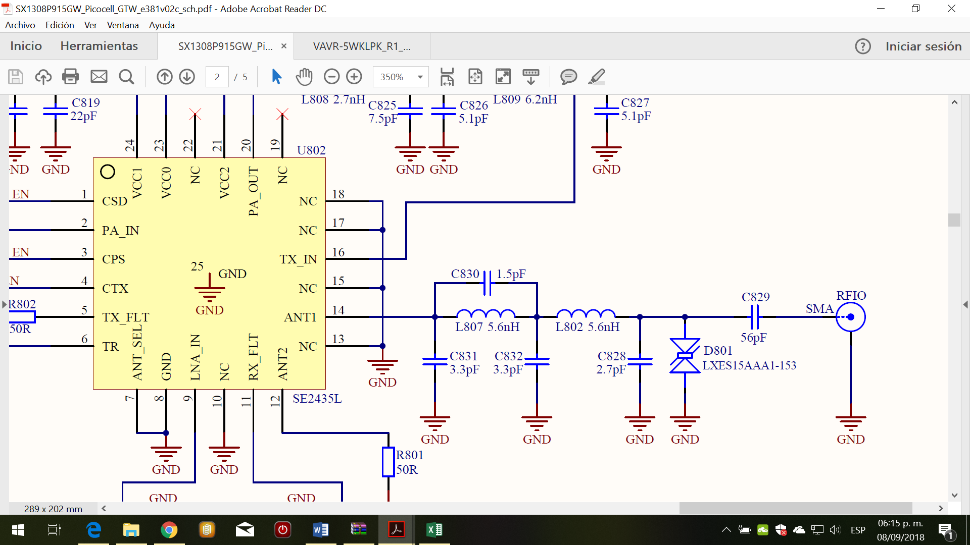
I see two differences between the Microchip design and the Semtech design:
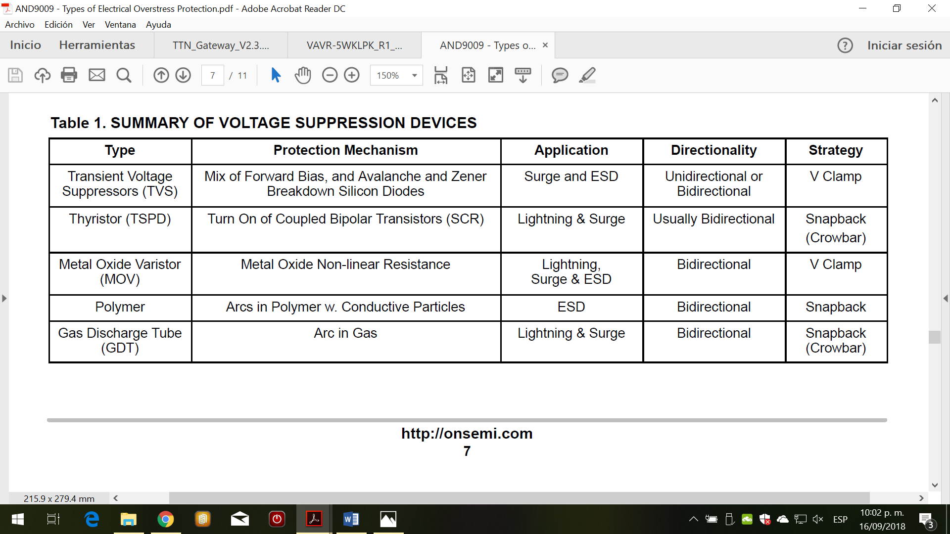
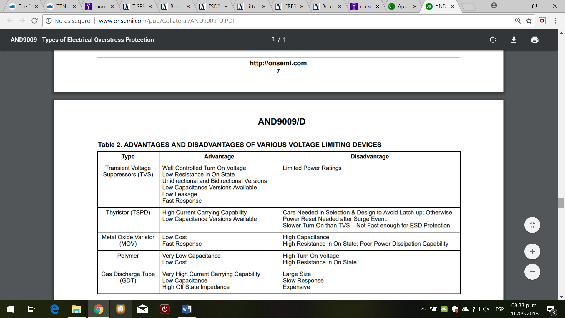
a) At the RF antenna part, the Semtech design has a ESD protection device (TVS D801 diode LXES15AAA1-153) and the Microchip don’t.
b) Instead LC passive components likes Semtech design, Microchip design uses the ceramic low pass filter U10 (0915LP15B026E).
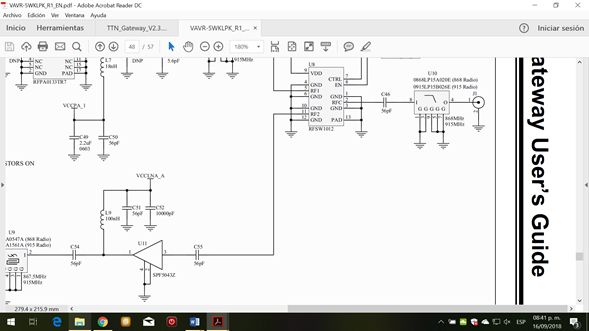
Microchip RF antenna part.
Semtech RF antenna part
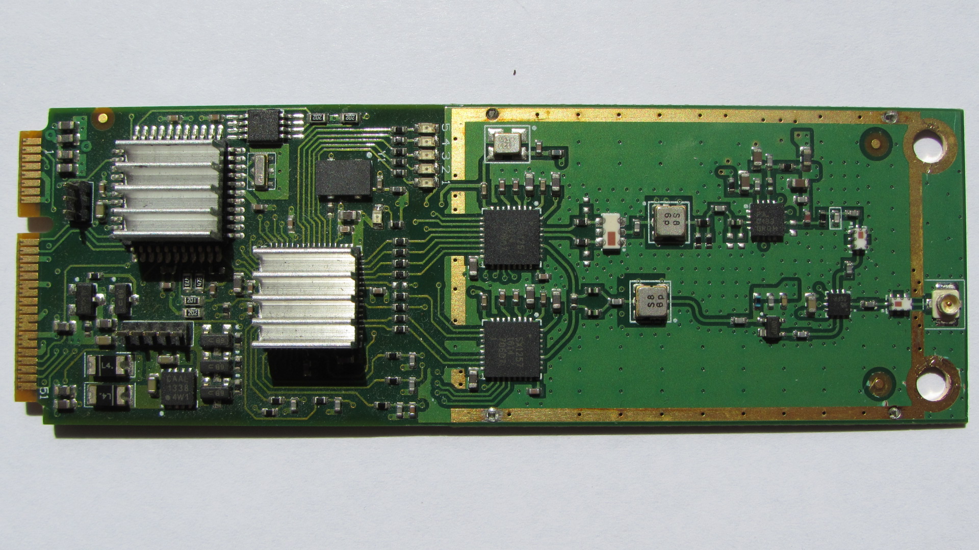
I removed the shielding of the LG9271 TTN GW RF module (mPCIe Smart Gateway card from Microchip/Occammd) and noted that the antenna section is similar than the Microchip LoRa Gateway design (with a ceramic filter and without a ESD protection device).
Finally, my questions are if the TTN GW LG9271 RF card is damaged because it doesn’t have the TVS diode as the Semtech reference design, what components do you recommend to change? (taking the Microchip LoRa Gateway schematic diagram as the LG9271 schematic diagram); and do you recommend to connect a ESD protection device likes the TVS diode LXES15AAA1-153 in all my TTN GW’s to avoid they lost range an RSSI by nearby lightning strike? or do you have a better solution?
Thanks.