Hamradio is all about experimenting, so why not build another antenna ?
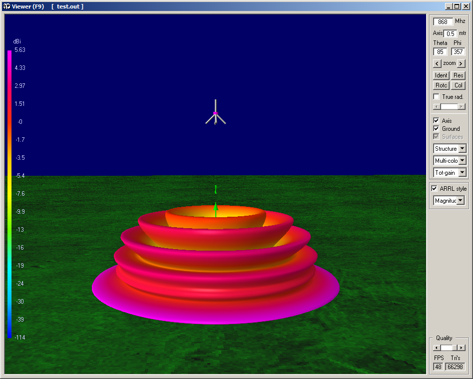
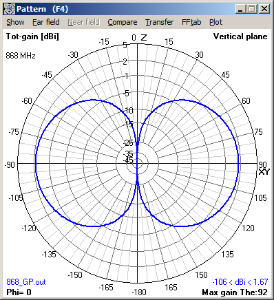
One of the most common antenna’s is the ground plane antenna which is basicly a 1/4 lambda driver element and 3 or 4 reflector elements (creating a artificial ground). It’s a simple antenna to build with a good bandwidth, it doesn’t have any gain over a dipole because it’s dipole. Ok for the record it has a +2.15dBi gain (so you 3$ ebay 5 dBi antenna only has a 2.85dB gain over a dipole) 
More info at : Electronic Design
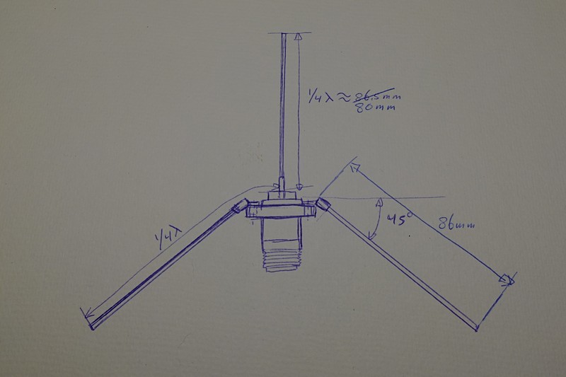
The design
Note : length adjusted for best SWR (see SWR measurement below).
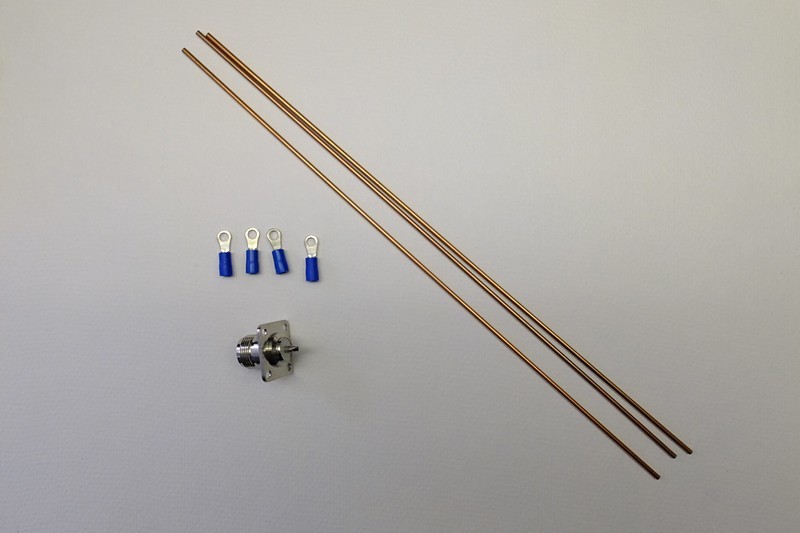
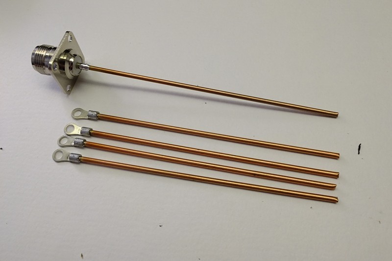
Materials used
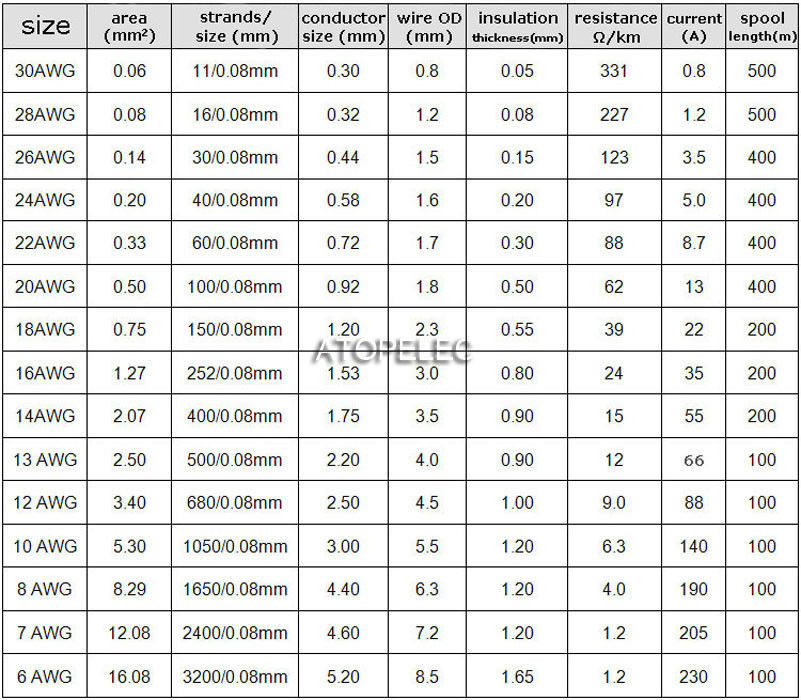
aprx 50cm of 2mm diameter brass or copper wire cut to 5 pieces of 10 cm.
4 x cable ends M4 / Blue
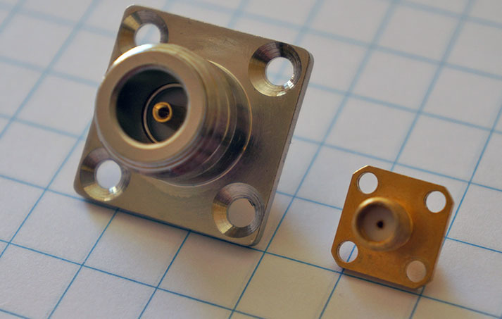
1 x N-style chassis part
4 x M4 10mm cylinder screws
4 x M4 lock nut.
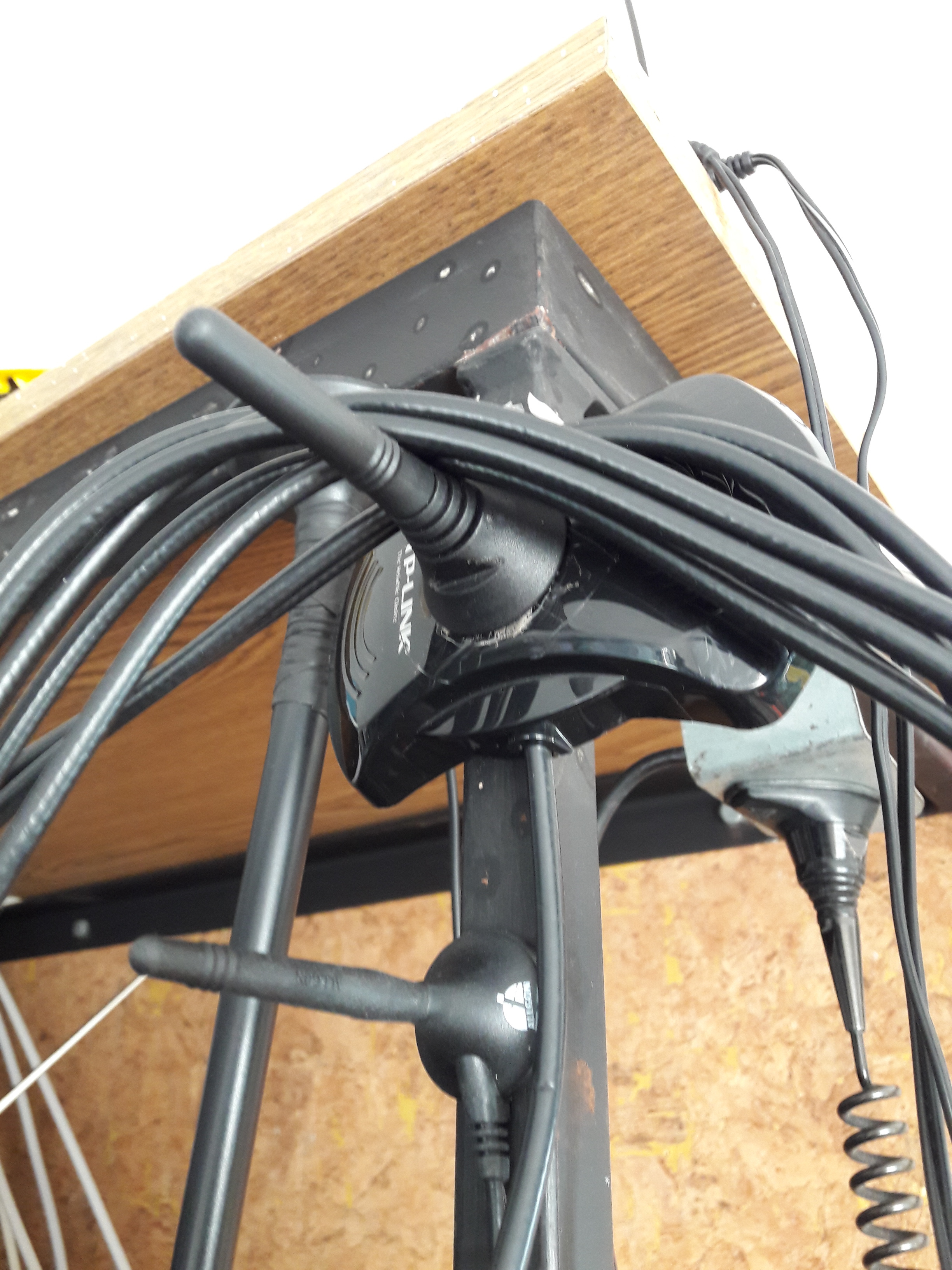
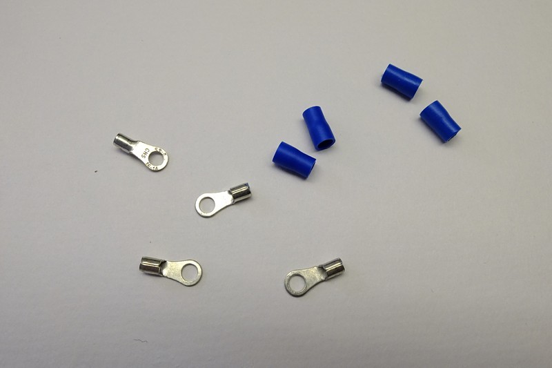
Step 1
Remove the blue plastic parts.
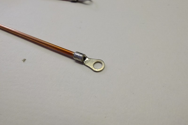
Step 2
Solder the cable ends to one end of the tubes.
Step 3
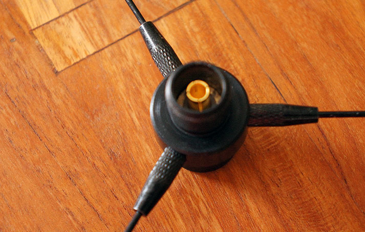
Solder the tube to the center pin of the chassis part.
Step 4
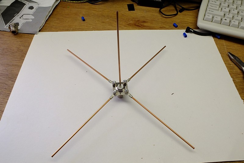
Mount the ground plane tubes to the chassis part with the M4 10mm screws and the M4 lock nut. And trim the tubes to the correct length (see : design).
Step 5
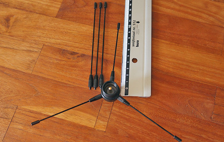
Bend the ground plane wires to a 45 degr. angle.
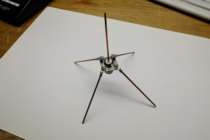
You’re almost done. When you want to use the groundplane antenna outdoor. Please apply a bit of silicone sealing around the top of the chassis part (so no water is collected on top).
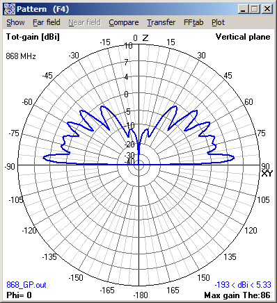
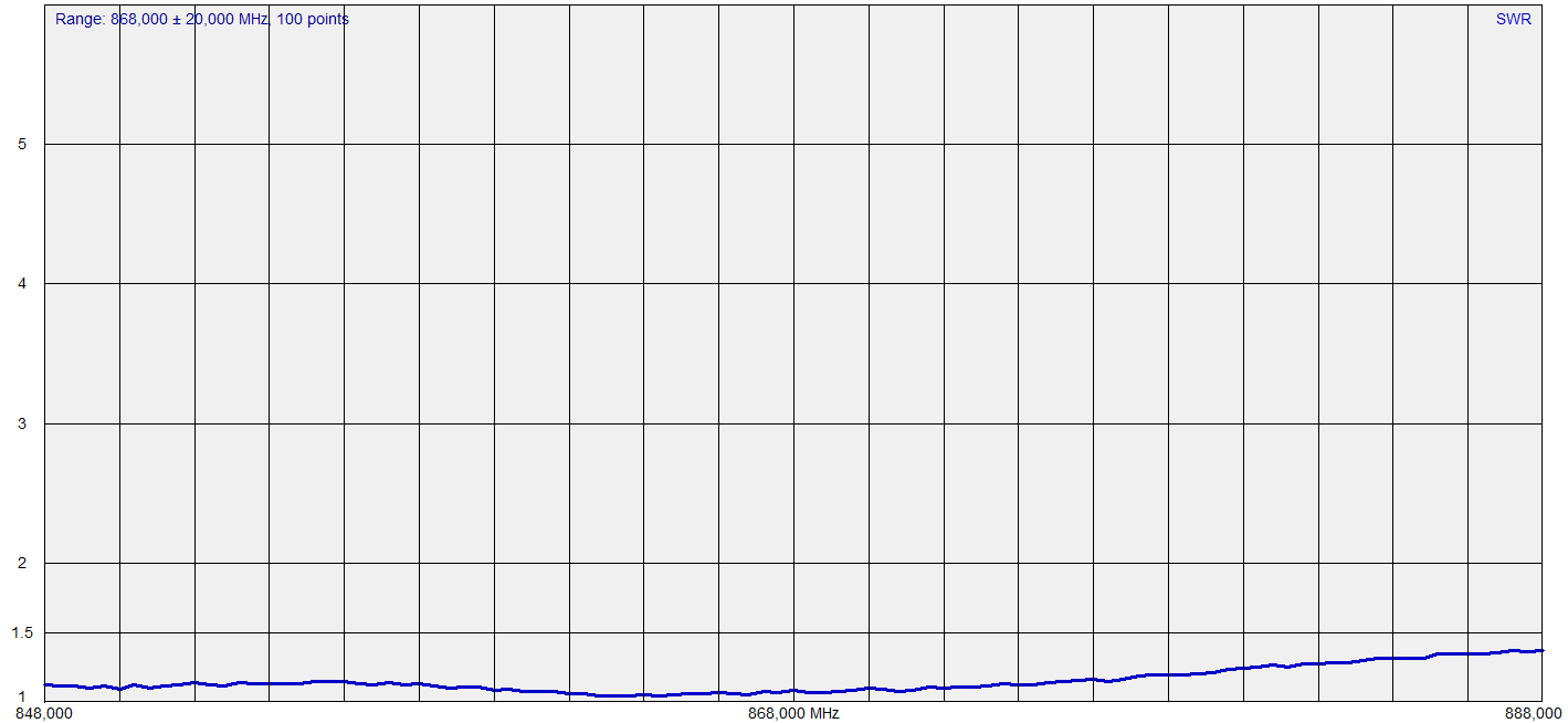
SWR measurment result
After the inital building I took the antenna to my local Hamradio club (Veron/VRZA Twente) to have it tested with a RigExpert AA-600 (which when connected to the computer can work up to 1.4Ghz) from a fellow Ham. Some minor tweaking (I made it for a lower frequency so I could trim it for the 868Mhz) the SWR dip was right on the 868Mhz.
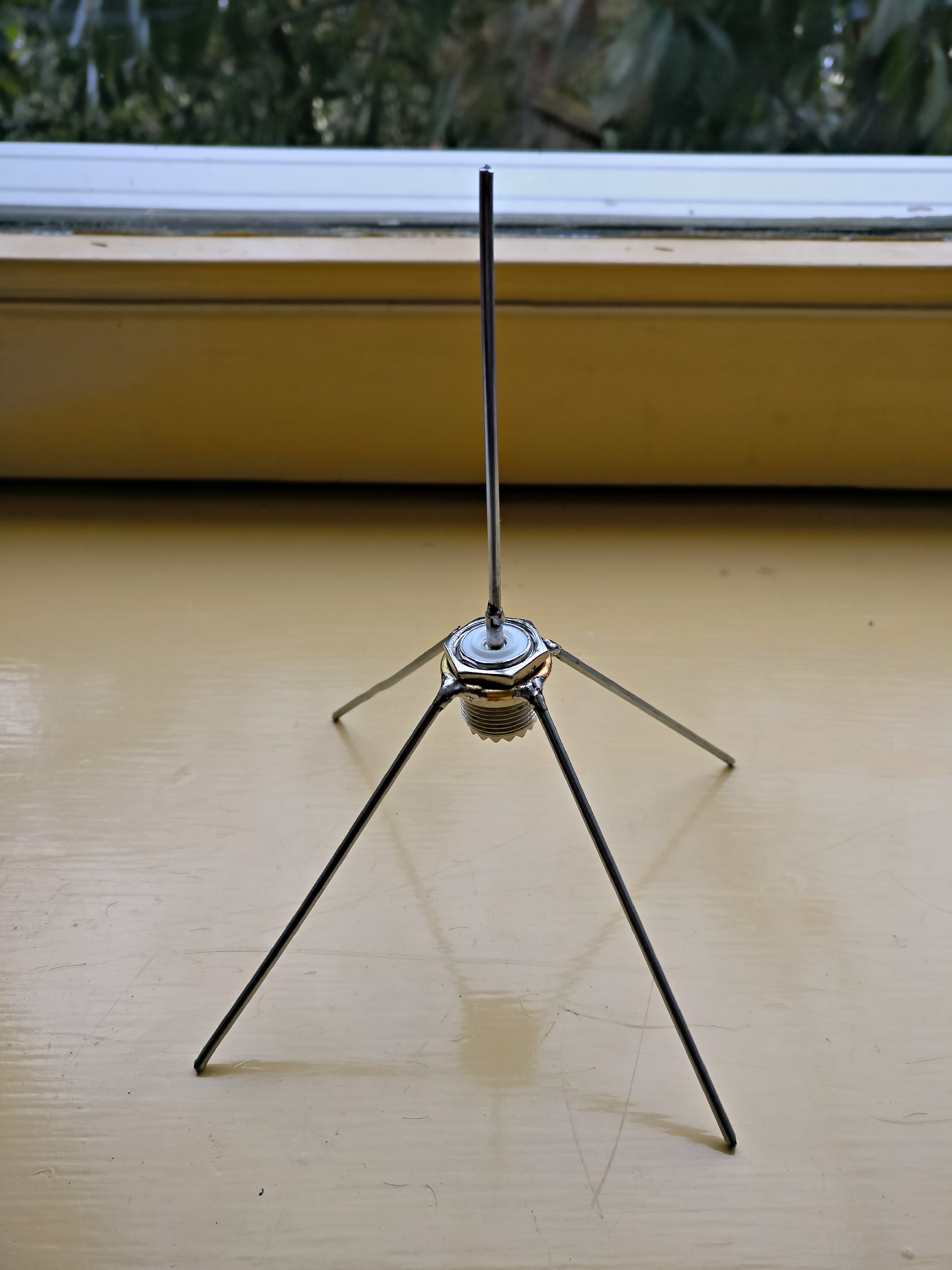
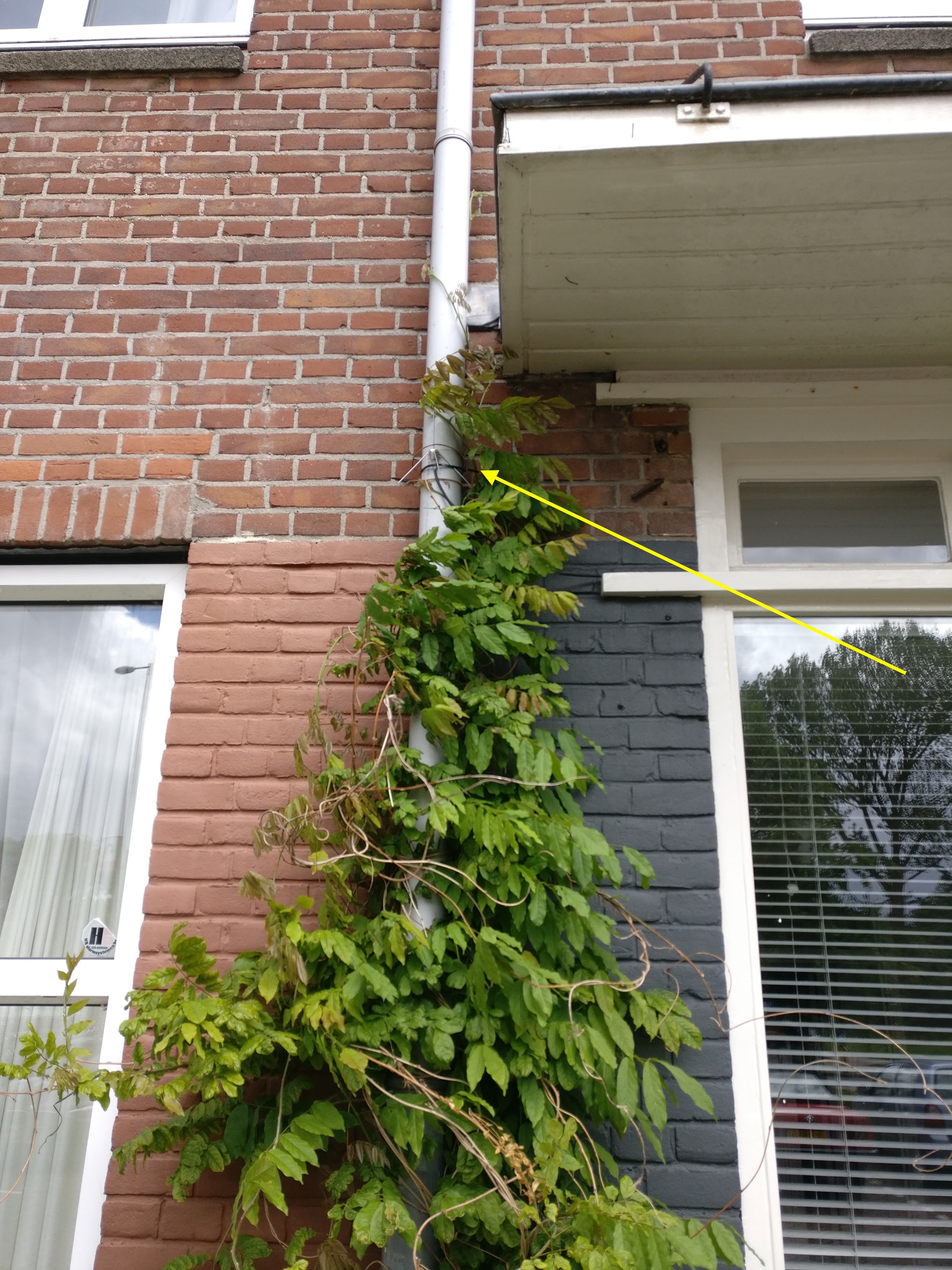
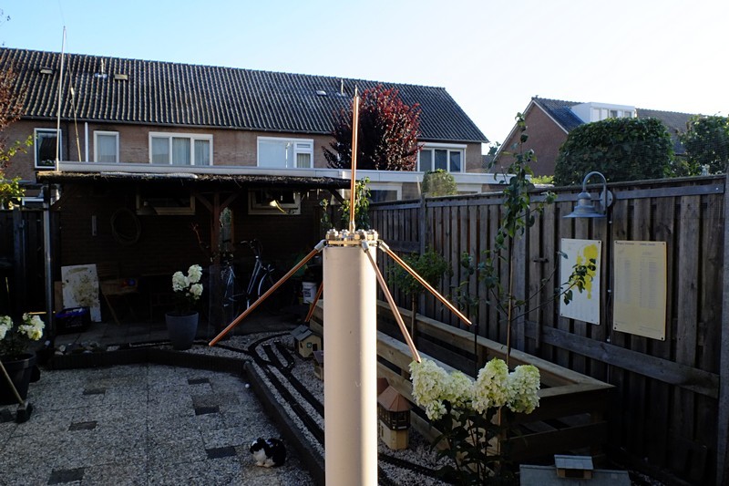
Installing
This groundplane antenna can be easily installed on a 32 mm PVC tube.The connected cable will pull the groundplane antenna to his place.
At this moment I can’t tell anything about the true signal response. I have to clime the roof to swap the antenna’s.
Note : I have written a LAB about it which you can find it on this link.

 you got me there. Indeed they should be longer aprx 10 cm.