May be a direct copy of the Semtech/iMST LoRaMote Mk1 PCB designs from 2014/2015…contact SMTC WSG Central Apps team or the guys at iMST - they may help…
You’re right, it looks very similar! I’ve sent an email to know restrictions regarding the usage. I’ll post here if they give it to me and under which condition 
Ok so the reference design is available on Semtech website as part of the Lora Community ressources. Direct link: https://www.semtech.com/uploads/documents/AN1200.20-SARANT_V1_0_STD.pdf
I asked the support to be sure and the design is free to use.
Yeh I forgot about the AN1200 series app notes - still have a copy of that one on file from years back…btw if interested there are others covering ref designs and the LoRa modulation basics etc. which may be of interest to anyone interested in LoRa background stuff (AN1200.19, .22, &.28 etc.), . The .20 incorporates a patch ant for use with the SX9500 proximity sensor for detection - use to adjust e.g. WiFi or BT (Or LoRa) Tx for meeting SAR requirements when close to body mass and also used with the original LoRaMOTE to put it into one of its prog/configuation modes (pinch patch during power up to trigger mode change )
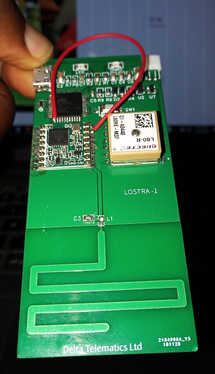
I implemented this design in single mode. From all tests, with obstacles in the path, performance is very similar to a 1/4 wave dipole. However with a clear path i see a the PCB antenna RSSI better than that of a dipole antenna by at least 10units.
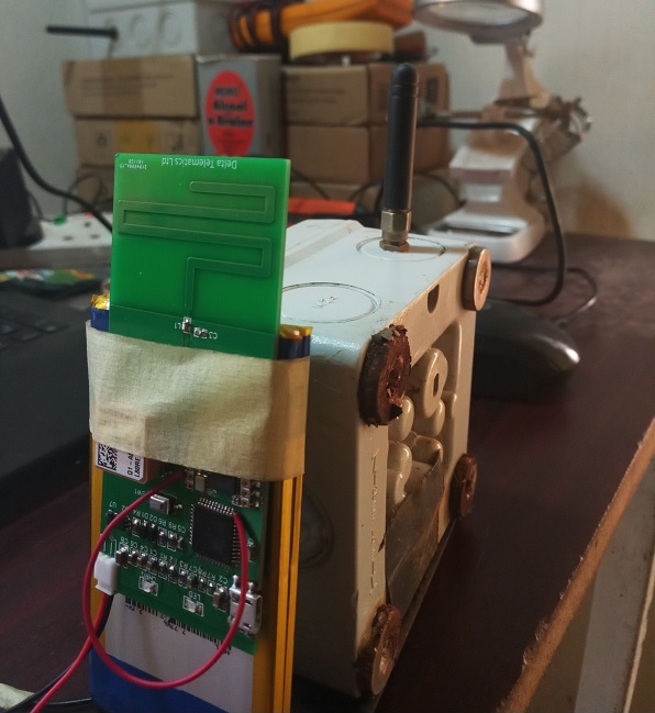
Here is a picture of both devices used in testing.
1 Like
UPDATE
This is an update on testing the LoRa tracker device with a PCB antenna, same one I mentioned was very similar to a 1/4 dipole with an obstructed path (through walls). Apparently that is so only at close range. The previous tests were with a gateway indoors and the node at different distances from the building or within it.
However I got a pleasant surprise today, while driving around with the device to rest the range within the city. I received packets on a gateway 3.7Km away while driving with the device placed on a car seat and in an urban area. None of the devices I have used previously tested has been able to achieve this. The maximum distance has been approximately 1.8Km.
For most practical purposes, a good PCB patch antenna is more effective than any other antenna of equal gain as it completely eliminates losses due to connectors, couplers and pigtails.
5 Likes
how did you choose L1 and C3?
The design note specified this on page 7. See link to the design note as posted by @BoRRoZ above.
Update
So far I have received signals from a moving vehicle 5.99KM away on SF12.
ah. ok.
so you didnt calculated the capacity on your own 
the upper wire (the end, L4) seems to be shorter as in the design note.
Is your antenna for 868MHz?
No i didn’t recalculate. Yes my antenna is 868MHz although on a double sided board, the bandwidth is wide (about 88MHz). From the design note, a chart shows the bandwidth with a SWR of 2.0 (-10 dB RL) is 913 MHz – 825MHz = 88 MHz. If L4 is full, the antenna will be tuned for dual mode (868MHz and 2440MHz). In this mode, the gain is lower (about 4.85dBi) according to the design note. However if L4 = L2 + W, the gain is higher (about 5.05dBi).
1 Like
I’ve looked at a number of the TI design notes and haven’t seen a 915MHz version of this same antenna. Does anyone know how to modify to 915MHz? Is it simply a matter of scaling the dimensions in the ratio 868/915?
Are you looking at getting 915MHz as center frequency?
If yes, how improvement in performance would this afford?
According to the design note, this Single band Option Design for 868 / 915 / 920 MHz. However from the graphs, it seems to have a center frequency a little below 868MHz. I would like to see a design that explains the calculations.
Yes, i’m looking to be centred on 915MHz or at least get good performance on this band. Remember 915Mhz is only the nominal frequency, the actual TTN operating frequencies are in the range 916MHz - 918MHz. So this is outside the 88MHz bandwidth which tops out at 913MHz.
Sir can u tell me what is successfuly achived range of http://www.ti.com/lit/an/swra416/swra416.pdf . This lora helical antena?
I’m designing a node which gets attached to outer wall of a building in “room side”. I’m seasoned HW designer but new to antenna design and trying to figure out what kind of design goals I should have for the antenna. Especially in terms of radiation pattern.
Should the antenna pattern be directed away from the wall (inside the room) or towards the wall (pointing outside of the building)? Or it doesn’t matter?
The PCB is flat against the wall about 5-10mm away from the wall. Is it feasible to use patch antenna on PCB in this case?
Hi @tipo1000, I believe that this is a very common design. The antenna directly on the PCB is, I think, often referred to as “meandering trace antenna”. Searching on Google gets lots of responses and companies like Texas Instruments have public reference designs, search for their Design Note 38, DN038.
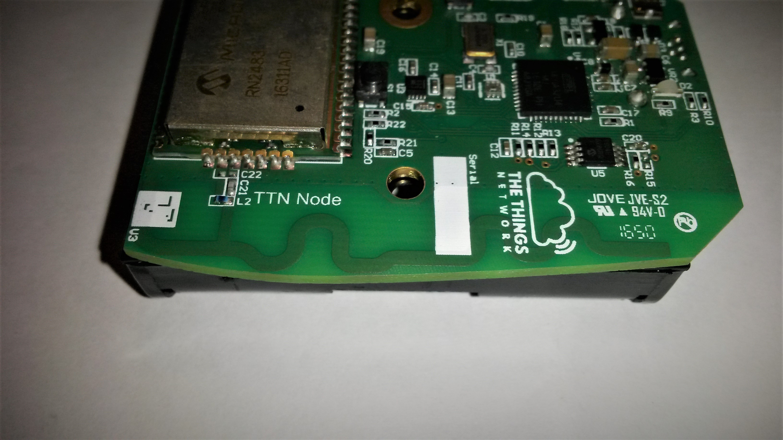
This is a picture of the PCB from a TTI “The Things Network Node” showing the meandering trace coming out of the RF module.