Hi, Im trying to change my RM186 BLE from central to peripherical. After reading all the posts you guys share from your successful experiences and contacting Laird for additional information, I’m not being able to connect my j-link base from Segger to the module.
I dont have the DVK(only the module) and I’m doing it with the 19 pin connector. Also I saw that Laird did an new release on the firmware, which got to new upgrades without new information. The main problem should be the pinout connection to the module, since I only got the 19 pin connector and the j-link does all correctly except he cant connect to the module.
I’ve been programming these via SWD recently (flashing from central to peripheral). I’ve used a NRF dev kit with jlink firmware, but a segger should also work. Working with a bare RM186, you need to wire pin22 (nreset) to SWDIO, pin23 (nc) to SWCLK, pin 24 (gnd) to gnd, and pin 12 (vcc) to VTref. Segger is programming via SWD. This assumes that you are powering the RM186 via a 3.3V supply as the Segger does not provide it. I then verify connection to the device using NRF Studio, you’ll be able to see the firmware layout on the RM186 if you connected fine, after that, I flashed using the firmware tool supplied by laird rather than using NRF studio.
Thank you for the information. I was trying JTAG pinout on j-link. Now I changed the pinout and connected all fine, but still not able to connect/identify the RM186. Could you explain me how you are doing it with the software?
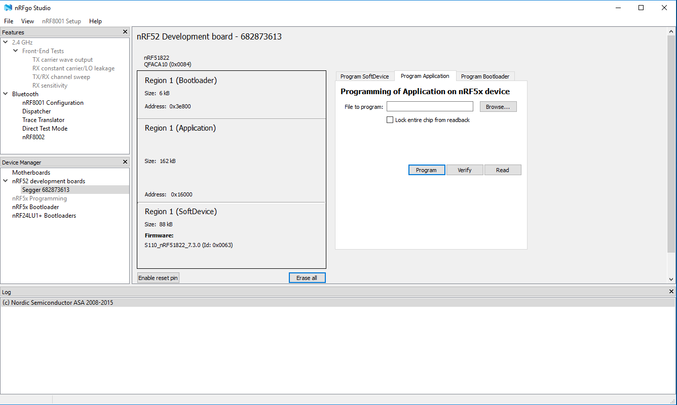
I use nRFgo Studio to verify the connection - as you see I’m using the a nordic NRF52 dev kit as my programmer and this is connected to the RM186 via SWD (P20 header connector). The NRF52 is setup with a jlink segger firmware. The photo shows the nRF51822 (the mcu on the RM186) listed and the layout of its firmware (bootloader, application and softdevice). I use this to make sure I’ve wired up my programmer correctly and that windows is able to see the device.
Next I followed the instructions included with the RM186 110.6.1.0 PE firmware - basically fire up an admin command prompt, navigate to the directory where the firmware is, and then “__LoadCombinedRM1xx_PE.bat 186_EU”.
Thank you so much for the help you providing. Unfortunatly I’m not being able to detect the RM186 yet, but I’m still trying to figure out why and meking sure the pinout is well connected.
For all the people struggling with flashing the firmware, you can flash it with OpenOCD and a cheap STLink (around 13€) via SWD, but the procedure is somehow dangerous so until I write a complete tutorial with some extra safety operations tested (i.e until I flash another module), I prefer to give it by PM to people that I know they know what they’re doing.
Also, if you are tired to flash with UWTerminalX for compiling, I wrote a command line tool in python, well it’s not that elegant (a lot of hardcoded values) , but if it can help somebody it’s here:
I just finished the firmware, and I’ve been driving all around testing it’s range. I can’t believe how far thing thing can go. I really enjoy smartBASIC, and was able to pick it up pretty fast. I love this little Laird module.
Hi all, this forum has been super helpful in my own development so thank you all.
I’ve got a problem running my smartBASIC applications whereby the device connects to the network and sends packets without issue while within range of the gateway but when I leave the range of the gateway and return it does not get back on the network.
I am using OTAA keys because I may have devices change networks, and my application contemplates the device leaving the network through the use of a global ‘joined’ variable that is manipulated in handlers. If the global is set low by handlers, it attempts to connect using OTAA on a timer and if the global is set hi it will transmit status on the same timer. I have a LED that flashes twice if connected and once if disconnected every 15 seconds based on the ‘joined’ variable state that does what is expected so I know the device is recognizing leaving the network it just doesn’t seem to want to talk to the gateway when it returns.
Is anyone successfully running a RM191 on Australian AU915. Starting with an example application from Laird, my RM191 transmits out of band (can see with SDR) but once it joins it reliably continues to send packets on the correct AU915 channels. Using the configuration at+cfgex 1009 “0002000000000000ff00” for AU915 and running version 102.6.1.0 (result of at i 3) I’m confused as once it joins the frequencies are correct. I have assumed if the channel configuration is wrong, after joining it would continue to use a combination of correct and incorrect channels.
Ahhh, that’s very interesting. The node must therefore be set for US915 not AU915, even though I’ve installed what I think is the AU version. Thanks @kersing
Solved, Thanks @kersing, found there is a configuration bit that determines if the RM191 follows the channel plan OR broadcasts on all 64 channels. Thanks again for a wonderful piece of information.
The boards aren’t available for purchase, this was my senior project. However if you want one, I’m sure we could work something out.
I’m not sure about sleep current. Both the GPS and the RM191 can be put into sleep mode, which I’ve never tried before. If you’re serious about finding out, I can look into it this weekend.