attachInterrupt(digitalPinToInterrupt(drv_pin), do_smth, mode)
Where are ‘drv_pin’ and ‘mode’ defined ?
attachInterrupt(digitalPinToInterrupt(drv_pin), do_smth, mode)
Where are ‘drv_pin’ and ‘mode’ defined ?
ah but it was a tiny typo 
attachInterrupt(digitalPinToInterrupt(drvn_pin), do_smth, FALLING);
    #include "PinChangeInterrupt.h" // https://github.com/NicoHood/PinChangeInterrupt this one

    const int drvPin = A2;
    const int DONEPin = A1;


    void setup() {
      // set pin to input with a pullup, DONE to output
      pinMode(drvPin, INPUT_PULLUP);
      pinMode(DONEPin, OUTPUT);

      Serial.begin(9600);

      attachPCINT(digitalPinToPCINT(drvPin), do_smth, FALLING); // DRV goes LOW, when TPL time has elapsed

      //ENABLE SLEEP - this enables the sleep mode
      SMCR |= (1 << 2); //power down mode
      SMCR |= 1;//enable sleep

    }


    bool sendData = true; // tracks if you need to send data
    void do_smth(void) {

      //say tahat you need to send data
      //nothing else goes here!
      sendData = true;
    }

    void loop() {
      if (sendData)
      {
        //here you read data, process it and send!

        Serial.println("Send data now");

        /*

            LORA SEND HERE

        */

        sendData = false; //so do_smth() can alter state;

        digitalWrite(DONEPin, HIGH); // reset TPL timer;
        delay(50); // have to test this on real Hardware
        digitalWrite(DONEPin, LOW); //so that TPL doesn't go to sleep at time it wakes.

        goToSleep();
      }
    }

    void goToSleep()
    {
      Serial.println("GOING TO SLEEP");
      Serial.flush();

      //BOD DISABLE - this must be called right before the __asm__ sleep instruction
      MCUCR |= (3 << 5); //set both BODS and BODSE at the same time
      MCUCR = (MCUCR & ~(1 << 5)) | (1 << 6); //then set the BODS bit and clear the BODSE bit at the same time
      __asm__  __volatile__("sleep");//in line assembler to go to sleep
    }
I don’t have HW, but try this out.
sendData probably should be volatile
OH mennn!!! seriously, you come and post your code just like this and it freaking work beautifully !!!
Well it does, it does work amazing, goes to sleep, wake up according the resistor value i set, it bring tears to my eyes !! Thanks, thanks a millions time, the first working code for the board v1.2 , you made it xD
Yes, but the code could not have been tested with the ‘typos’ in place.
Dont forget to take the serial prints out of the interrupt service routine, as the tutorial suggested.
Gregleguenec Be great now you have 1.2 ver working,can you publish the full code so others can use. say on Git Hub
Si
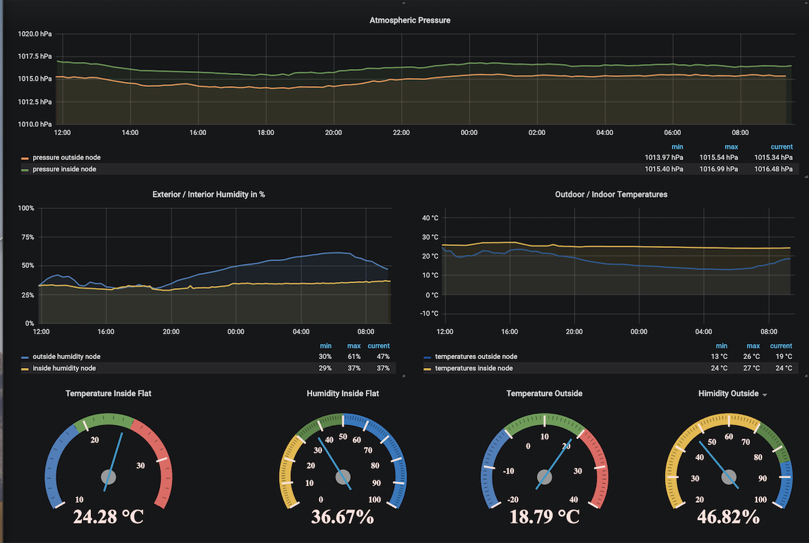
Sure, but i don’t use LMIC nor TTN network, since all i need to monitor are my rooms temp/humidity, i have my own custom gateway pushing from lora >> udp >> influxdb (grafana) self hosted.
So you will need to adapt the code and change LoRa lib to LMIC if you wanna join TTN network
So there you go:
#include <SPI.h>
#include <LoRa.h>
#include <Wire.h>
#include <Arduino.h>
#include <rBase64.h>
#include <ArduinoJson.h>
#include <Adafruit_Sensor.h>
#include <Adafruit_BME280.h>
#include "PinChangeInterrupt.h"

// BME280
#define SEALEVELPRESSURE_HPA (1013.25)
//LORA
#define NSS    10
#define RST     A0
#define DI0     2
#define SCK     13
#define MISO    12
#define MOSI    11
#define BAND  868E6
#define BLUE_LED 13
#define SF_FACTOR 7

const int drvPin = A2;
const int DONEPin = A1;
bool sendData = true;
Adafruit_BME280 bme;

void do_smth(void) {
  sendData = true;
}

void setup() {
  if (! bme.begin(0x76)) {
	while (1);
  }

  bme.setSampling(Adafruit_BME280::MODE_FORCED,
		    Adafruit_BME280::SAMPLING_X1, // temperature
		    Adafruit_BME280::SAMPLING_X1, // pressure
		    Adafruit_BME280::SAMPLING_X1, // humidity
		    Adafruit_BME280::FILTER_OFF   );
  delay(10);

  LoRa.setPins(SS,RST,DI0);
    if (!LoRa.begin(BAND)) {
      while (1);
    }
  LoRa.setSpreadingFactor(SF_FACTOR);
  // set pin to input with a pullup, DONE to output
  pinMode(drvPin, INPUT_PULLUP);
  pinMode(DONEPin, OUTPUT);

  attachPCINT(digitalPinToPCINT(drvPin), do_smth, FALLING); // DRV goes LOW, when TPL time has elapsed

  //ENABLE SLEEP - this enables the sleep mode
  SMCR |= (1 << 2); //power down mode
  SMCR |= 1;//enable sleep

}

void goToSleep()
{
  LoRa.sleep();

  ADCSRA &= ~(1 << 7);
  //BOD DISABLE - this must be called right before the __asm__ sleep instruction
  MCUCR |= (3 << 5); //set both BODS and BODSE at the same time
  MCUCR = (MCUCR & ~(1 << 5)) | (1 << 6); //then set the BODS bit and clear the BODSE bit at the same time
  __asm__  __volatile__("sleep");//in line assembler to go to sleep
}

void loop() {

  if (sendData)
  {
    bme.takeForcedMeasurement();

    const size_t capacity = JSON_OBJECT_SIZE(4);
    DynamicJsonDocument doc(capacity);
    String output;
    doc["t"] =  bme.readTemperature();
    doc["h"] = bme.readHumidity();
    doc["p"] = bme.readPressure() / 100.0F;

    serializeJson(doc, output);
    // For local test puropse, it's enough, to make it prod ready, use AES !!!
    rbase64.encode(output);
    LoRa.beginPacket();
    LoRa.print(rbase64.result());
    LoRa.endPacket();

    sendData = false; //so do_smth() can alter state;

    digitalWrite(DONEPin, HIGH);
    delay(1);
    digitalWrite(DONEPin, LOW);

    goToSleep();
  }
}
For sure, you can make much prettier with some more love and patience.
Regarding battery consumption, i put a 2.5 ohm resistor in serie and tried to measure the voltage drop, thus deducing the current.
With BME280 and rfm95W WITHOUT sleep mode ~2.3 mA
With BME280 and rfm95W WITH sleep mode , i can’t measure as my UT61E give me 0.00 mV, thus, all i know is that i’m under 4 uA
PS: I would like to thanks all those helped me, but a special thanks to @jenertsA for helping on the TPL code !
Lots of sad faces.
Yes i understand, but the fairplay policy is a mess, let’s agree, i would need sometimes to push every 5 min, sometimes in SF7, soon some other nodes on some mountain’s top (~70km away) in SF12, meaning crazy amount of air time per day.
And i don’t get the idea of publishing stuff on internet while all you need can be run in local env Anyway, just my opinion
The fair access plocy is not broken, it just sets a limit on what you get for free.
If the free access is not enough for you, contact the things network industries where you can pay for more.
If a node needs ‘crazy amount of air time per day’ then you would could well be breaking the legal duty cycle limit of 1%.
i still have a tiny issue, this code works perfectly and consume 2-3 uA in sleep
#include "PinChangeInterrupt.h"

const int drvPin = A2;
const int DONEPin = A1;
bool sendData = true;


void setup() {
  attachPCINT(digitalPinToPCINT(drvPin), do_smth, FALLING); // DRV goes LOW, when TPL time has elapsed

  SMCR |= (1 << 2); //power down mode
  SMCR |= 1;//enable sleep
}

void goToSleep()
{
  ADCSRA &= ~(1 << 7);
  //BOD DISABLE - this must be called right before the __asm__ sleep instruction
  MCUCR |= (3 << 5); //set both BODS and BODSE at the same time
  MCUCR = (MCUCR & ~(1 << 5)) | (1 << 6); //then set the BODS bit and clear the BODSE bit at the same time
  __asm__  __volatile__("sleep");//in line assembler to go to sleep
}

void loop() {

  if (sendData)
  {
    sendData = false; //so do_smth() can alter state;
    digitalWrite(DONEPin, HIGH); // reset TPL timer;
    delay(1);
    digitalWrite(DONEPin, LOW); //so that TPL doesn't go to sleep at time it wakes.

    goToSleep();
  }
}
But if i add @Charles library for checking the voltage
#include  "adcvcc.h"
#include "PinChangeInterrupt.h"

const int drvPin = A2;
const int DONEPin = A1;
bool sendData = true;


ISR(ADC_vect)
{
  _adc_irq_cnt++;
}

void setup() {
  attachPCINT(digitalPinToPCINT(drvPin), do_smth, FALLING); // DRV goes LOW, when TPL time has elapsed

  SMCR |= (1 << 2); //power down mode
  SMCR |= 1;//enable sleep
}

void goToSleep()
{
  ADCSRA &= ~(1 << 7);
  //BOD DISABLE - this must be called right before the __asm__ sleep instruction
  MCUCR |= (3 << 5); //set both BODS and BODSE at the same time
  MCUCR = (MCUCR & ~(1 << 5)) | (1 << 6); //then set the BODS bit and clear the BODSE bit at the same time
  __asm__  __volatile__("sleep");//in line assembler to go to sleep
}

void loop() {

  if (sendData)
  {
    int batt = (int)(readVcc() / 100);
    byte batvalue = (byte)batt;

    sendData = false; //so do_smth() can alter state;
    digitalWrite(DONEPin, HIGH); // reset TPL timer;
    delay(1);
    digitalWrite(DONEPin, LOW); //so that TPL doesn't go to sleep at time it wakes.

    goToSleep();
  }
}
In sleep mode, the arduino consume around 4 mA!! Does anyone have any explanations why this library consume so much current ?
Thanks you 
ok here you can continue now about pin interrupts
aren’t we in the topic about this board ? coz then we all did  Some new people would probably want to know how to fix issues related to this board, there is already someone asking about the TPL code, this way we can keep enriching this topic i’d say Thanks to that, we have now a working code for the board 1.2 that the whole community and new comers can enjoy
Thank you, very helpful!