** 4/12/17 - Altered to take into account what Kersing says below
** 7/12/17 - Altered to take into account the installation of libraries that may not already be installed and to add sister TX code
** 15/12/17 - Altrered to add info on how to copy the 3 codes from console
1) Single Channel Gateway using Heltec WiFi LoRa 32 (with OLED display)
Thanks @Kersing
Got the single channel gateway working on my Heltec WiFi LoRa 32 (with OLED display)
https://www.aliexpress.com/item/868MHz-915MHz-SX1276-ESP32-LoRa-0-96-Inch-OLED-Display-Bluetooth-WIFI-Lora-Kit-32-Module/32835492243.html?ws_ab_test=searchweb0_0,searchweb201602_1_10152_10065_10151_10344_10068_10130_10345_10324_10342_10547_10325_10343_10340_10341_10548_10192_10541_10190_10084_10083_10307_10301_10303_10539_10312_10059_10313_10314_10184_10534_100031_10604_10603_10103_10605_10594_10596_10142_10107,searchweb201603_25,ppcSwitch_5&algo_expid=2ba45802-8bfd-4728-b9ca-e592aea6c379-19&algo_pvid=2ba45802-8bfd-4728-b9ca-e592aea6c379&rmStoreLevelAB=5
Very nice
Just listing the things I did to get it working (hopefully useful for others)
- install Arduino IDE https://www.arduino.cc/en/Main/Software
- install ESP8266 core as per github https://github.com/esp8266/Arduino
- install ESP32 core as per github https://github.com/espressif/arduino-esp32
- Execute the Arduino IDE and goto “File->Preferences” and make a note of the “Sketchbook Location”. This is the “stub” folder which you will reference when loading folders/files (we will call it STUB from now on) It is usually something like “C:\Users???\Documents\arduino”.
- Download ZIP file from https://github.com/kersing/ESP-1ch-Gateway-v5.0
- Extract the ZIP file (preferably using 7-zip http://www.7-zip.org/ )
- Copy everything from the extracted file folder “libraries” and paste into STUB\libraries"
- Copy folder “ESP-sc-gway” from the zip file and paste into “STUB\libraries”
- Go to “STUB\libraries\ESP-sc-gway\ESP-sc-gway.h” and alter the code using “wordpad”.
You need to update the following 3 sections
1 Gateway Ident definitions
(description, Lat long)
2 ntp
(for UK, change to NTP_TIMESERVER “uk.pool.ntp.org” and NTP_TIMEZONES 0
3 definition of wpas wpa[]
Change code from this:
#if 0
wpas wpa[] = {
{ “” , “” }, // Reserved for WiFi Manager
{ “ape”, “apePasswd” }
{ “ape”, “apePasswd” }
};
#else
Place outside version control to avoid the risk of commiting it to github 
#include “d:\arduino\wpa.h”
#endif
to this
wpas wpa[] = {
{ “” , “” }, // Reserved for WiFi Manager
{ “YOUR WIFI SSID”, “YOUR WIFI SSID PASSWORD” }
};
-
Execute the Arduino IDE
-
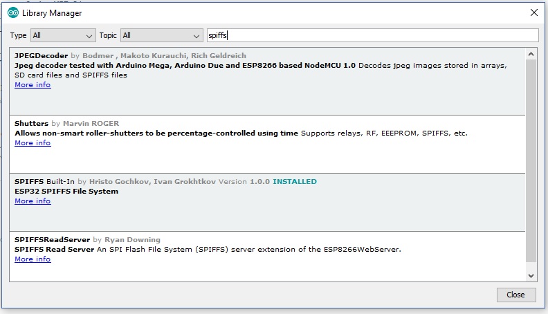
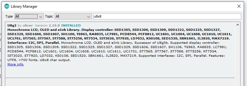
Ensure you have installed both the SPIFFS and U8G2 libraries as shown (ignore the others shown in this pic) using “Sketch->Include Library->Manage Libraries”
-
Upload the sketch via “File->Examples->ESP-sc-gway”. Set up the port and upload into your Heltec WiFi LoRa 32 device, (when the device re-boots, you should see info displayed on the OLED)
-
When the device has booted and logged into your wifi network, find the IP address it is using from your router and enter this IP address into a web browser to display a webpage of Gateway details - note the 8 byte “Gateway ID” (you need this for the TTN console)
-
Log into the TTN console and setup a new gateway - You need to tick the “I’m using the legacy packet forwarder” checkbox and paste the 8 byte “Gateway ID” seen from the webpage.
-
setup a few other things like frequency and save!
-
thats it - amazing !!!
2) Example TX code for HelTec Lora (for use with Gateway above)
- Download the zip file for LMIC https://github.com/matthijskooijman/arduino-lmic
- unzip and rename folder “arduino-lmic-master” to “arduino-lmic” (there can be a clash with other versions of the “LMIC” library)
- Put the renamed “arduino-lmic” folder into the STUB/libraries
- (optional) If you have version problems when compiling the code, try removing the standard library called “IBM_LMIC_framework” from STUB/libraries (you can easily put it back using Sketch->Include Library->Manage Libraries)
Copy and paste the preformatted text seen below into the Arduino IDE.
The 3 lines that need changing are prefixed with “$$”. Remove the “$$” and replace the code using info defined in TTN - remember that in TTN, you can only switch the device from OTAA to ABP after you have saved the device in TTN!!! Once the device has been changed to “ABP”, you will then see the 3 codes in the console that you need to copy back to the Arduino code. i.e.
For DEVADDR/Device Address - just copy the hex and add after the 0x in the code
For NWKSKEY and APPSKEY - click the eye (show code) then the <> (C-style), click the “copy” button and then use that to paste into the code (do not press the ⇆ button and check that your showing MSB before copying!)
/*******************************************************************************
 * Copyright (c) 2015 Thomas Telkamp and Matthijs Kooijman
 * adapted by Curlywurly to use LCD
 * Permission is hereby granted, free of charge, to anyone
 * obtaining a copy of this document and accompanying files,
 * to do whatever they want with them without any restriction,
 * including, but not limited to, copying, modification and redistribution.
 * NO WARRANTY OF ANY KIND IS PROVIDED.
 *
 * This example sends a valid LoRaWAN packet with payload "Hello,
 * world!", using frequency and encryption settings matching those of
 * the The Things Network.
 *
 * This uses ABP (Activation-by-personalisation), where a DevAddr and
 * Session keys are preconfigured (unlike OTAA, where a DevEUI and
 * application key is configured, while the DevAddr and session keys are
 * assigned/generated in the over-the-air-activation procedure).
 *
 * Note: LoRaWAN per sub-band duty-cycle limitation is enforced (1% in
 * g1, 0.1% in g2), but not the TTN fair usage policy (which is probably
 * violated by this sketch when left running for longer)!
 *
 * To use this sketch, first register your application and device with
 * the things network, to set or generate a DevAddr, NwkSKey and
 * AppSKey. Each device should have their own unique values for these
 * fields.
 *
 * Do not forget to define the radio type correctly in config.h.
 *
 *******************************************************************************/

#include <lmic.h>
#include <hal/hal.h>
#include <SPI.h>
#include <U8x8lib.h>

#define BUILTIN_LED 25

// the OLED used
U8X8_SSD1306_128X64_NONAME_SW_I2C u8x8(/* clock=*/ 15, /* data=*/ 4, /* reset=*/ 16);


// LoRaWAN NwkSKey, network session key
// This is the default Semtech key, which is used by the early prototype TTN
// network.
$$static const PROGMEM u1_t NWKSKEY[16] = { 0xAA, 0xCE, 0x88, 0x69, 0x05, 0xC6, 0xCE, 0xEF, 0x33, 0xF4, 0x76, 0xDC, 0xDC, 0x77, 0x67, 0x9F };

// LoRaWAN AppSKey, application session key
// This is the default Semtech key, which is used by the early prototype TTN
// network.
$$static const u1_t PROGMEM APPSKEY[16] = { 0x86, 0xF9, 0xB8, 0xC6, 0x69, 0x70, 0x63, 0x37, 0xCA, 0x12, 0xE0, 0x8D, 0xFF, 0xEC, 0x6A, 0xAA };

// LoRaWAN end-device address (DevAddr)
$$static const u4_t DEVADDR = 0x310313D8 ; // <-- Change this address for every node!

// These callbacks are only used in over-the-air activation, so they are
// left empty here (we cannot leave them out completely unless
// DISABLE_JOIN is set in config.h, otherwise the linker will complain).
void os_getArtEui (u1_t* buf) { }
void os_getDevEui (u1_t* buf) { }
void os_getDevKey (u1_t* buf) { }

static uint8_t mydata[] = "Hi!";
static osjob_t sendjob;

// Schedule TX every this many seconds (might become longer due to duty
// cycle limitations).
const unsigned TX_INTERVAL = 10;

// Pin mapping
const lmic_pinmap lmic_pins = {
    .nss = 18,
    .rxtx = LMIC_UNUSED_PIN,
    .rst = 14,
    .dio = {26, 33, 32},
};

void onEvent (ev_t ev) {
    Serial.print(os_getTime());
    u8x8.setCursor(0, 5);
    u8x8.printf("TIME %lu", os_getTime());
    Serial.print(": ");
    switch(ev) {
        case EV_SCAN_TIMEOUT:
            Serial.println(F("EV_SCAN_TIMEOUT"));
            u8x8.drawString(0, 7, "EV_SCAN_TIMEOUT");
            break;
        case EV_BEACON_FOUND:
            Serial.println(F("EV_BEACON_FOUND"));
  u8x8.drawString(0, 7, "EV_BEACON_FOUND");
            break;
        case EV_BEACON_MISSED:
            Serial.println(F("EV_BEACON_MISSED"));
  u8x8.drawString(0, 7, "EV_BEACON_MISSED");
            break;
        case EV_BEACON_TRACKED:
            Serial.println(F("EV_BEACON_TRACKED"));
  u8x8.drawString(0, 7, "EV_BEACON_TRACKED");
            break;
        case EV_JOINING:
            Serial.println(F("EV_JOINING"));
  u8x8.drawString(0, 7, "EV_JOINING");
            break;
        case EV_JOINED:
            Serial.println(F("EV_JOINED"));
  u8x8.drawString(0, 7, "EV_JOINED ");
            break;
        case EV_RFU1:
            Serial.println(F("EV_RFU1"));
  u8x8.drawString(0, 7, "EV_RFUI");
            break;
        case EV_JOIN_FAILED:
            Serial.println(F("EV_JOIN_FAILED"));
  u8x8.drawString(0, 7, "EV_JOIN_FAILED");
            break;
        case EV_REJOIN_FAILED:
            Serial.println(F("EV_REJOIN_FAILED"));
  u8x8.drawString(0, 7, "EV_REJOIN_FAILED");
            break;
        case EV_TXCOMPLETE:
            Serial.println(F("EV_TXCOMPLETE (includes waiting for RX windows)"));
            u8x8.drawString(0, 7, "EV_TXCOMPLETE");
            digitalWrite(BUILTIN_LED, LOW);
            if (LMIC.txrxFlags & TXRX_ACK)
              Serial.println(F("Received ack"));
            u8x8.drawString(0, 7, "Received ACK");
            if (LMIC.dataLen) {
              Serial.println(F("Received "));
    u8x8.drawString(0, 6, "RX ");
              Serial.println(LMIC.dataLen);
    u8x8.setCursor(4, 6);
    u8x8.printf("%i bytes", LMIC.dataLen);
              Serial.println(F(" bytes of payload"));
    u8x8.setCursor(0, 7);
    u8x8.printf("RSSI %d SNR %.1d", LMIC.rssi, LMIC.snr);
            }
            // Schedule next transmission
            os_setTimedCallback(&sendjob, os_getTime()+sec2osticks(TX_INTERVAL), do_send);
            break;
        case EV_LOST_TSYNC:
            Serial.println(F("EV_LOST_TSYNC"));
  u8x8.drawString(0, 7, "EV_LOST_TSYNC");
            break;
        case EV_RESET:
            Serial.println(F("EV_RESET"));
  u8x8.drawString(0, 7, "EV_RESET");
            break;
        case EV_RXCOMPLETE:
            // data received in ping slot
            Serial.println(F("EV_RXCOMPLETE"));
  u8x8.drawString(0, 7, "EV_RXCOMPLETE");
            break;
        case EV_LINK_DEAD:
            Serial.println(F("EV_LINK_DEAD"));
  u8x8.drawString(0, 7, "EV_LINK_DEAD");
            break;
        case EV_LINK_ALIVE:
            Serial.println(F("EV_LINK_ALIVE"));
  u8x8.drawString(0, 7, "EV_LINK_ALIVE");
            break;
         default:
            Serial.println(F("Unknown event"));
  u8x8.setCursor(0, 7);
  u8x8.printf("UNKNOWN EVENT %d", ev);
            break;
    }
}

void do_send(osjob_t* j){
    // Check if there is not a current TX/RX job running
    if (LMIC.opmode & OP_TXRXPEND) {
        Serial.println(F("OP_TXRXPEND, not sending"));
u8x8.drawString(0, 7, "OP_TXRXPEND, not sent");
    } else {
        // Prepare upstream data transmission at the next possible time.
        LMIC_setTxData2(1, mydata, sizeof(mydata)-1, 0);
        Serial.println(F("Packet queued"));
u8x8.drawString(0, 7, "PACKET QUEUED");
digitalWrite(BUILTIN_LED, HIGH);
    }
    // Next TX is scheduled after TX_COMPLETE event.
}

void setup() {
    Serial.begin(115200);
    Serial.println(F("Starting"));
  u8x8.begin();
  u8x8.setFont(u8x8_font_chroma48medium8_r);
  u8x8.drawString(0, 1, "HelTec TX LMiC");

#ifdef VCC_ENABLE
    // For Pinoccio Scout boards
    pinMode(VCC_ENABLE, OUTPUT);
    digitalWrite(VCC_ENABLE, HIGH);
    delay(1000);
    #endif
SPI.begin(5, 19, 27);
// LMIC init
os_init();
    // Reset the MAC state. Session and pending data transfers will be discarded.
    LMIC_reset();
   // Set static session parameters. Instead of dynamically establishing a session
    // by joining the network, precomputed session parameters are be provided.
    #ifdef PROGMEM
    // On AVR, these values are stored in flash and only copied to RAM
    // once. Copy them to a temporary buffer here, LMIC_setSession will
    // copy them into a buffer of its own again.
    uint8_t appskey[sizeof(APPSKEY)];
    uint8_t nwkskey[sizeof(NWKSKEY)];
    memcpy_P(appskey, APPSKEY, sizeof(APPSKEY));
    memcpy_P(nwkskey, NWKSKEY, sizeof(NWKSKEY));
    LMIC_setSession (0x1, DEVADDR, nwkskey, appskey);
    #else
    // If not running an AVR with PROGMEM, just use the arrays directly
    LMIC_setSession (0x1, DEVADDR, NWKSKEY, APPSKEY);
    #endif
   #if defined(CFG_eu868)
    // Set up the channels used by the Things Network, which corresponds
    // to the defaults of most gateways. Without this, only three base
    // channels from the LoRaWAN specification are used, which certainly
    // works, so it is good for debugging, but can overload those
    // frequencies, so be sure to configure the full frequency range of
    // your network here (unless your network autoconfigures them).
    // Setting up channels should happen after LMIC_setSession, as that
    // configures the minimal channel set.
    // NA-US channels 0-71 are configured automatically
    LMIC_setupChannel(0, 868100000, DR_RANGE_MAP(DR_SF12, DR_SF7),  BAND_CENTI);      // g-band
    LMIC_setupChannel(1, 868300000, DR_RANGE_MAP(DR_SF12, DR_SF7B), BAND_CENTI);      // g-band
    LMIC_setupChannel(2, 868500000, DR_RANGE_MAP(DR_SF12, DR_SF7),  BAND_CENTI);      // g-band
    LMIC_setupChannel(3, 867100000, DR_RANGE_MAP(DR_SF12, DR_SF7),  BAND_CENTI);      // g-band
    LMIC_setupChannel(4, 867300000, DR_RANGE_MAP(DR_SF12, DR_SF7),  BAND_CENTI);      // g-band
    LMIC_setupChannel(5, 867500000, DR_RANGE_MAP(DR_SF12, DR_SF7),  BAND_CENTI);      // g-band
    LMIC_setupChannel(6, 867700000, DR_RANGE_MAP(DR_SF12, DR_SF7),  BAND_CENTI);      // g-band
    LMIC_setupChannel(7, 867900000, DR_RANGE_MAP(DR_SF12, DR_SF7),  BAND_CENTI);      // g-band
    LMIC_setupChannel(8, 868800000, DR_RANGE_MAP(DR_FSK,  DR_FSK),  BAND_MILLI);      // g2-band
    // TTN defines an additional channel at 869.525Mhz using SF9 for class B
    // devices' ping slots. LMIC does not have an easy way to define set this
    // frequency and support for class B is spotty and untested, so this
    // frequency is not configured here.
    #elif defined(CFG_us915)
    // NA-US channels 0-71 are configured automatically
    // but only one group of 8 should (a subband) should be active
    // TTN recommends the second sub band, 1 in a zero based count.
    // https://github.com/TheThingsNetwork/gateway-conf/blob/master/US-global_conf.json
    LMIC_selectSubBand(1);
    #endif
// Disable link check validation
    LMIC_setLinkCheckMode(0);
// TTN uses SF9 for its RX2 window.
    LMIC.dn2Dr = DR_SF9;
// Set data rate and transmit power for uplink (note: txpow seems to be ignored by the library)
    LMIC_setDrTxpow(DR_SF7,14);
// Start job
    do_send(&sendjob);
    pinMode(BUILTIN_LED, OUTPUT);
    digitalWrite(BUILTIN_LED, LOW);

}

void loop() {
    os_runloop_once();}