Big ESP32 / SX127x topic part 1

So I received that SX1278 / 433Mhz one I ordered by error : https://fr.aliexpress.com/item/SX1278-LoRa-ESP32-0-96-inch-Blue-OLED-Display-Bluetooth-WIFI-Lora-Kit-32-Module-Internet/32831131677.html?isOrigTitle=true

Anyone in an appropriate region to use it who wants it, I’ll send it for the cost of shipping - from France.

Edit : no longer available, it went to someone in Germany.

1 Like

@nicbkw and Heltec 868 MHz users,

Anyone made a ready to use package or published a github with the Arduino code and libraries for testing the Heltec 868 MHz device with LoRaWAN?

Cheers.

OK, I got my Heltec LoRa boards today. No secret, I am not a programmer but I have tried to duplicate what you have done to make the libraries work… I can’t get it to work!
First issue I have is the declaration in oslmic.h , it is done per your hint but I get a compile error.

C:\Users\Garry\Documents\Arduino\libraries\arduino-lmic-master\src\hal\hal.cpp: In function ‘void hal_io_check()’:

C:\Users\Garry\Documents\Arduino\libraries\arduino-lmic-master\src\hal\hal.cpp:66:32: error: ‘radio_has_irq’ was not declared in this scope

         if ( radio_has_irq() ) 

                            ^

Would you have a suggestion what I have done wrong? I have declared it below…

// Dependencies required for the LoRa MAC in C to run.
// These settings can be adapted to the underlying system.
// You should not, however, change the lmic.[hc]

…at line 83, is this glaringly wrong?

Thanks, Garry

Hi - just use https://github.com/matthijskooijman/arduino-lmic and set Pin mapping like this (thanks to @bluejedi)

// Pin mapping
const lmic_pinmap lmic_pins = {
    .nss = 18,
    .rxtx = LMIC_UNUSED_PIN,
    .rst = 14,
    .dio = {26, 33, 32},
};

Mapping all 3 DIO pins means there is no need to change the LMiC library as I described.

3 Likes

@nicbkw Much obliged for your help, first attempt at OTAA and with the new ESP32 board. Now to wade out of my depth with some sensors and possibly even the OLED! Thanks again…

Joined

Garry

1 Like

My Heltec board has a helical wire antenna for 2.4GHz on top, not the PCB antenna.
It also has a PCB antenna on the bottom side but that antenna is not connected.
The helical antenna sticks out above the display, not handy if to be mounted in a case.
WiFi reception with the helical antenna is poor. I was only able to detect 9 WiFi networks (max), while at the same location an ESP8266 ESP-12F module with PCB antenna detects 28 networks (max).
I wanted to improve the antenna so I hacked the PCB. I removed the helical wire antenna and mounted an U.FL connector so I can connect different types of antennas. This was possible because the antenna pad is surrounded with ground traces. While the modification is still not as good as the ESP-12F, I was able to detect 14 WiFi networks (max), which is an improvement of more than 50% (in detected networks).
I tried several 2.4GHz antennas, including 2 PCB types and a regular foldable type with SMA connector but the model shown on the picture below performed best.
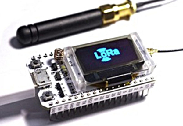
4GHz antenna
Original

4GHz 600x360
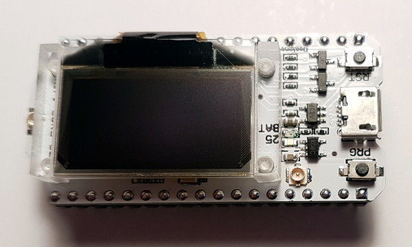
With U.FL connector mounted
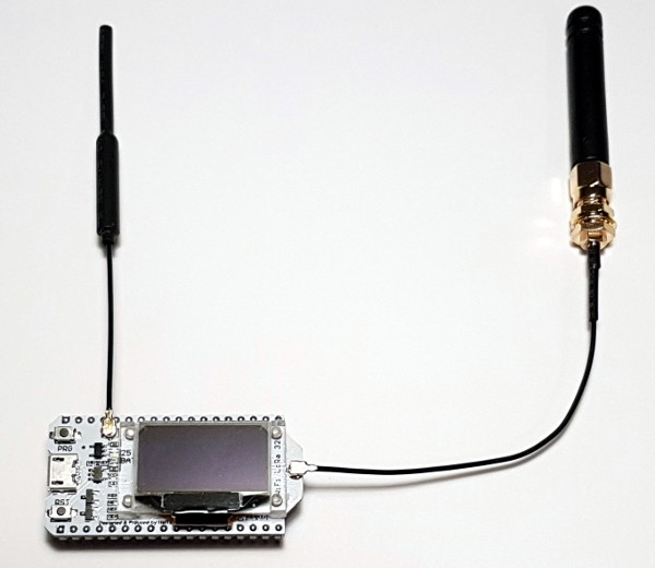
4GHz with antennas 600x520
With antennas

1 Like

To use the OLED is quite simple. Add this in the header of your Arduino script:

#include <U8x8lib.h>

// the OLED used
U8X8_SSD1306_128X64_NONAME_SW_I2C u8x8(/* clock=*/ 15, /* data=*/ 4, /* reset=*/ 16);

Add this in your setup()

u8x8.begin();
u8x8.setFont(u8x8_font_chroma48medium8_r);

Then to display data on the OLED, use something like this:

      u8x8.setCursor(0, 7);
      u8x8.printf("RSSI %d SNR %.1d", LMIC.rssi, LMIC.snr);
3 Likes

I would like to run a run a single channel gateway on this board (preferably with multi-SF and OTAA support).
Has any single channel gateway implementation been ported to ESP32 already?

Update:

YES
See ‘List of single channel gateway implementations’ here: Single Channel Gateway part 2

2 Likes

Hmm, I was quite sure their GitHub repo was already mentioned here, but no… So:

And some asides:

  • The EU868 units I got all seem to be running the File > Examples > LoRa Function Basic Test > OLED_LoRa_Sender sketch, but then using #define BAND 868E6. So, to use OLED_LoRa_Receiver, change the value for band in the example sketch.

  • To make the receiver examples see the TTN LoRaWAN 868.1, use #define BAND 868.1E6.

  • Using LoRa.onReceive(callback) does not work for me; calling LoRa.parsePacket() within loop() works fine though.

  • The orange battery LED is flashing like crazy; maybe attaching a battery makes it stop? @DeuxVisdocument claims: “The orange LED lights will go out when the battery is full”:

    image

  • The same document also says: “To use the on-board IO port with touch function as the touch signal input (WIFI Kit32 and LoRa 32 with this function), add a 100 nF pulldown capacitor to this pin.”

2 Likes

A battery connector/cable was not included. Any idea what connector type the battery connector is? It is smaller than JST-PH connectors.

DeuxVis’ document does not give much details, but:

LITHIUM BATTERY INTERFACE 2Pin-1.25mm

And:

Onboard lithium battery charge and discharge circuit, The orange LED lights will go out when the battery is full , only provide the basic lithium battery charging and discharge function, can not monitor the battery temperature and power, if your battery is not purchased in our shop, Please pay attention to the battery positive and negative, wrong operation may explode.

And the HelTec website shows:

They sell the cable but that doesn’t provide much further detail either.

Looking at your picture, it looks like they use a MCP73831 (or compatible) charging IC (the 5-pin SOT23 below the helical coil). The default behaviour of the STAT pin is to blink while charging (or no battery connected) and to turn off when battery is full.

This is from one of my designs, which also uses a green led to indicate battery full.

2 Likes

Some more interesting ‘nuts and bolts’ hacking at the Espressif chips by Andreas Spiess, this time getting both processor cores of the ESP32 working using the Arduino IDE only. Seems like this can only help with more complex tasks?

1 Like

I ordered micro JST off Ebay and they work fine. Downside is that they come in pairs, so I now have a number of micro JST male in-line connectors…

Which exact model is ‘Micro JST’?
I am unable to locate it on the JST site: JST Product Selection Guide
None of their 1.25mm connectors looks like the one on the Heltec board.

I think that the Heltect board uses a Molex PicoBlade Header:
1.25mm Pitch PicoBlade Header, Surface Mount, Right Angle, 2 Circuits

Cables Assemblies:
PicoBlade-to-PicoBlade Off-the-Shelf (OTS) Cable Assembly, Single Row, 2 Circuits

25mm PicoBlade 2 Circuit Cable Assembly

I ordered ebay item 232485892646 - it is just described as micro JST 1.25mm. They fit fine - pic below shows one alongside my test rig that is now being powered by a LiPo.

image

2 Likes

Good to hear that these ‘JST 1.25mm’ connectors do fit.

25mm PicoBlade 2 Circuit Cable Assembly
Molex PicoBlade 1.25mm

25mm female cable assembly
‘JST 1.25mm’

I have added a link for ‘JST 1.25mm’ cable assemblies in the Bargain Basement: The BARGAIN basement part 3

I was very interested to see the video about using both of the main cores of the ESP32 (https://youtu.be/k_D_Qu0cgu8), but even more excited to see in the comments an example sketch using the ULP - ESP32: ULP LED Hart beat and read DHT22 sensor · GitHub - to try this you will need to have installed the current ESP32 hardware support for your Arduino IDE - GitHub - espressif/arduino-esp32: Arduino core for the ESP32

Has anyone managed to get the power usage of these modules below 10ma? Even in deep sleep and with wifi/BT off I can’t manage it with a battery. Are they maybe using a low efficiency regulator that keeps on switching?

Received mine finally.
The antenna is quite different looking from what was in the aliexpress pictures.
They also provided a miniature heatsink - probably for the ESP32 chip ?

Wifi Lora Kit 32 868 - package

Now I must find some time to play with this…

1 Like