Wow. You are a genius! Not specifying the SDA and SCL Pins (leaving SDA, SCL in) did the trick.
I thought it does not matter as without the os_init() it worked like that:
U8G2_SSD1306_128X64_NONAME_F_SW_I2C u8g2(U8G2_R0, /* clock=/ PB6, / data=/ PB7, / reset=*/ PB5);
But with it only works with:
U8G2_SSD1306_128X64_NONAME_F_SW_I2C u8g2(U8G2_R0, /* clock=/ SCL, / data=/ SDA, / reset=*/ PB5);
U8g2 and U8x8 constructors
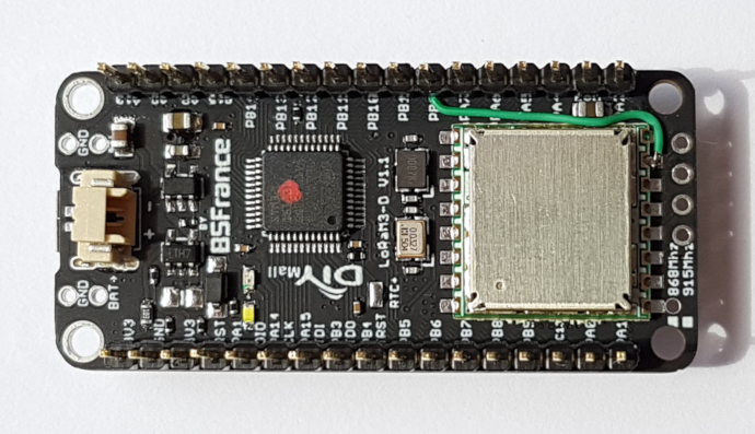
For the display on the BSFrance LoRaM3-D boards, the following U8g2 and U8x8 constructors can be used (they use hardware I2C).
Tip: Use default values / automatic configuration where possible.
For U8x8:
    // No need to specify SCL and SDA, the default values
    // are already defined in the board definition.
    U8X8_SSD1306_128X64_NONAME_HW_I2C display(/*reset*/ PB5);

    // This is in fact identical to the above.
    U8X8_SSD1306_128X64_NONAME_HW_I2C display(/*reset*/ PB5, /*clock*/ SCL, /*data*/ SDA);

    // Same as above but explicitly specifies the GPIO ports to use for SCL and SDA.
    U8X8_SSD1306_128X64_NONAME_HW_I2C display(/*reset*/ PB5, /*clock*/ PB6, /*data*/ PB7);
For U8g2 (using full buffer):
    // No need to specify SCL and SDA, the default values
    // are already defined in the board definition.
    U8G2_SSD1306_128X64_NONAME_F_HW_I2C display(U8G2_R0, /*reset*/ PB5);

    // This is in fact identical to the above.
    U8G2_SSD1306_128X64_NONAME_F_HW_I2C display(U8G2_R0, /*reset*/ PB5, /*clock*/ SCL, /*data*/ SDA);

    // Same as above but explicitly specifies the GPIO ports to use for SCL and SDA.
    U8G2_SSD1306_128X64_NONAME_F_HW_I2C display(U8G2_R0, /*reset*/ PB5, /*clock*/ PB6, /*data*/ PB7);
Have you tried the constructors described in above U8g2/U8x8 constructors post? These constructors should all work (tested on F103).
I have no access to my F103 the coming week but I will try and post the result. SW I2C worked but HW would be better, obviously.
Hello,
I have bought 2 BSFrance L151 board to use with Lora, but can’t manage to retrieve the battery voltage on pin PA1. I saw some of you have this board, did you manage to retrieve it?
Thanks for the help,
What do you mean with “can’t manage to retrieve the battery voltage”, does it only return 0?
I tried int value = analogRead(PA1); which should work but it only returns 0.
(Is this a BSFrance-stm32 core issue?)
While searching for a solution I noticed the following:
- STM32L151 ADC’s are 12-bit but the BSFrance-stm32 core appears to use only 10-bit resolution.
- On a different Arduino Core (‘Maple’, not for LoRaM3-D) a port must explicitly be set for analog input with
pinMode(pin, INPUT_ANALOG)but this does not work with the BSFrance-stm32 core.
FYI:
PA1 is connected via a voltage divider: a 100k resistor to Battery Plus (BAT+) and a 100k resistor to ground. So the voltage on PA1 is only 50% of the battery voltage.
With no battery connected I measure 4.1V on BAT+ (and 2V on PA1).
LoRaM3-D L151. Added a wire from DIO1 to PB0 so that DIO1 is permanently wired.
(Only DIO0 is wired on the board but LMIC requires both DIO0 and DIO1.)
On the bottom side to keep the display side free from wires.
3 Likes
Can’t edit above post anymore so I do it here:
Forget the remark ‘aka stm32duino’ because it is incorrect and confusing.
Arduino cores for STM32 (and naming confusion)
Forum
There is a special forum for Arduino and STM32: Arduino for STM32
“Everything relating to using STM32 boards with the Arduino IDE”.
This forum also hosts dedicated sections for specific Arduino cores.
See: http://www.stm32duino.com/
Arduino and cores
Arduino is a popular open source hardware and software ecosystem for developing microcontroller applications. It was originally developed for educational purposes.
The Arduino ecosystem consists of a runtime with standard API’s for running applications, an integrated development environment called the Arduino IDE that includes compilers (C/C++), tools for uploading and libraries.
The source code of an Arduino application is called a sketch. The sketch, software libraries and the Arduino runtime are all compiled into a single binary file that is then uploaded to the microcontroller board.
The Arduino core in principle is the Arduino framework runtime code that is required to run an Arduino application. Originally Arduino only supported 8-bit AVR microcontrollers but when it was ported to other microcontroller platforms like ARM Cortex M (SAMD21 and STM32), ESP8266 and ESP32, that also required different compilers and tools. Therefore the term Arduino core now not only refers to the runtime, but also to the compilers, tools, libraries, board definitions etc., that are required for a specific microcontroller (family).
Cores can be provided by microcontroller manufacturers, by board manufacturers, by individuals or by a community. Cores are installed via the Arduino IDE Boards Manager (when supported) or can be installed from files from the core’s Github repository.
Arduino cores for STM32
There are several Arduino cores available for the STM32 family of microcontrollers. The most relevant ones are described below. Compatibility and supported features of these cores can be different so they are not fully compatible. Ech core supports a limited set of boards. Some boards (e.g. bluepill) are supported by multiple cores while others (e.g. LoRaM3-D) are only supported by a single core.
Arduino STM32
Roger Clark’s popular Arduino STM32 core is a derivative of libmaple (GitHub - leaflabs/libmaple: [INACTIVE] C and C++ library for STM32 ARM Cortex-M3 development boards.) which was first developed by LeafLabs for their Maple and Maple mini boards. LibMaple and hence Arduino STM32 only supports the STM32F103 series of microcontrollers. This core directly accesses the hardware registers and is therefore difficult to port to other microcontrollers from the STM32 family. This is one of the older and more mature cores.
This core can be installed either using the files from github or via a Boards Manager package.
See: https://github.com/rogerclarkmelbourne/Arduino_STM32
In the Arduino Boards Manager this core is listed as “STM32F1xx/GD32F1xx boards by stm32duino”.
In the Tools/Board dropdown its supported boards are listed under “STM32 Boards (STM32duino.com)”.
Bootloader:
Roger Clark also developed a special bootloader known as the STM32duino bootloader. It is available for different STM32 F103 based boards and supports automatic uploading from sketches via USB. GitHub - rogerclarkmelbourne/STM32duino-bootloader: Bootloader for STM32F103 boards, for use with the Arduino_STM32 repo and the Arduino IDE
Arduino Core STM32
STM have produced an Arduino Core, which now supports multiple microcontrollers from the STM32 family of products. The core is based on the STM HAL, which makes it easier to support and port to other members of the STM32 family. This core is relatively new but it is at least supported by ST-Microelectronics, the manufacturer of the STM32. For the STM32F103 series the USB DFU upload method is not supported.
This core can be installed either using the files from github or via a Boards Manager package.
See: https://github.com/stmduino/Arduino_Core_STM32
The term stm32duino is already used by Roger’s ‘Arduino STM32’ core and bootloader so using stm32duino as the Github user name and location for the repository of the completely different ‘Arduino Core STM32’ core is unsmart and utterly confusing (unless the other STM32 cores would also be hosted under the stm32duino Github account, but that probably isn’t going to happen).
In the Arduino Boards Manager this core is listed as “STM32 Cores by ST-Microelectronics”.
In the Tools/Board dropdown its supported boards are listed under “STM32 Boards (selected from submenu)”.
STM32GENERIC
‘A generic implementation of Arduino for STM32 boards’. This core (developed by Daniel Fekete) also uses the STM HAL, but the structure and architecture of the core differs from STM’s implementation.
There is no Boards Manager package for this core so it has to be manually installed using the files from github. See: https://github.com/danieleff/STM32GENERIC and https://danieleff.github.io/STM32GENERIC/
In the Tools/Board dropdown its supported boards are listed under “STM32GENERIC for STM32 boards”.
BSFrance-stm32
This core from BSFrance is specific for their LoRaM3-D boards. This core is also based on the STM HAL and it appears to be based on a fork of STM32GENERIC.
There is no Boards Manager package for this core (yet) so it has to be manually installed using the files from github. See: https://github.com/BSFrance/BSFrance-stm32
In the Tools/Board dropdown its supported boards (currently) are listed under “STM32(HALMX & LL)”.
PlatformIO support
I haven’t had a good look at Arduino + STM32 support in PlatformIO yet, but there is support for it.
PlatformIO shows ‘ST STM32’ as a supported platform with ‘framework-arduinoststm32’ as an available package, but it is not clear which of the above Arduino cores for STM32 are supported.
At least Roger’s ‘Arduino STM32’ core appears supported because I have an LMIC LoRa example working in PlatformIO with the ‘bluepill’ board using the USB DFU upload method. (The BSFrance-stm32 core is not currently supported in PlatformIO.)
3 Likes
Hi bluejedi and thanks for your answer.
I indeed try to do a simple:
vbat = analogRead(PA1);
which returned 0. Also tried with pinMode(PA1, INPUT_ANALOG) which led to a compilation error
And also tried to use adc_read, which was not recognized neither.
I measured half of my lipo voltage on the Vbat pin (1.9V), on both my boards so problem should be on the software / library side.
I looked at the ADC part of the library (BSFrance-stm32/stm32/cores/arduino/stm32/stm32_ADC.c at master · BSFrance/BSFrance-stm32 · GitHub), and tried to force resolution to 12bits, and to force ADC enable with
__HAL_RCC_ADC1_CLK_ENABLE();
But in the end, I still cannot read the value of it.
Any idea ?
No, waiting on response from BSFrance. I suspect it could be an issue in their core.
Ok. Keep in the loop when you get the solution 
Thanks !
When you try exactly this:
int analogValue = analogRead(PA1);
Does this return 0 for analogValue, or was the 0 maybe the result from calculating the actual voltage?
(I had this problem somewhere during my testing.)
I have it working now, but I have tried and tested so many things that I do not remember what exactly fixed it.
I have first done some tests with a bluepill board because that allowed me to test with different cores: ‘Arduino STM32’, ‘Arduino Core STM32’ and STM32GENERIC.
On the bluepill I used PA1 for the measurements and added a 2x100k voltage divider, similar to the LoRaM3-D boards.
Arduino STM32 on bluepill worked. It uses the full 12-bit ADC resolution (max value: 4093).
Arduino Core STM32 on bluepill also worked but uses only 10 bits resolution (max value 1023), it’s readings were around 10% too low.
STM32GENERIC failed to compile without errors when I included #include <U8x8lib.h> so I didn’t bother to try it any further.
It now also works with BSFrance-stm32 and a LoRaM3-D F103 board. BSFrance-stm32 also uses only 10-bit ADC resolution.
With no battery connected and powered via USB (from computer) the multimeter measured a constant 2.007V on PA1, but analog read reported values fluctuating between 507 and 600+ (around 1.64 to 1.95V).
When battery connected (LiPo) to the battery connector and no USB connected, the multimeter measured a constant 1.864V on Pa1 and analog read is more stable, reporting values between 539 and 542 (1.74 to 1.75V).
#define ANALOG_MAX_VALUE 1023    // 1023 for 10-bit resolution, 4093 for 12-bit resolution
int analogValue = analogRead(PA1);
float voltage = analogValue * (3.3 / ANALOG_MAX_VALUE);
@bluejedi
OK, it is a bit late as the section moved forward to other topics, but I can confirm that HW I2C works as you describe on my F103.
1 Like
Hi
New challenge that I am facing today: Get a Waveshare e-Paper (1.54") running on the F103.
Yes, I know there is an OLED so what do I need a ePaper for …
And yes, could even be off-topic because it has not specifically to do with the radio part.
Thing is: With the Radio-module sitting on SPI, I am not sure if it is me, the library … why it won’t work.
And I always struggle with SPI, I2C seems to be easier to handle. Less wires maybe.
The soonuse-library https://github.com/soonuse/epd-library-arduino looked promising, simple and straight forward, so I gave it a try. Starting with the Pin description:
3.3V --> 3V3
GND --> GND
DIN --> D11
CLK --> D13
CS --> D10
DC --> D9
RST --> D8
BUSY --> D7
… it is easy to change some in the epdif.h.
like that:
#define RST_PIN PA8
#define DC_PIN PA0
#define CS_PIN PB14
#define BUSY_PIN PB9
These should be free to choose except DIN (MOSI) and CLK (SCLK)
I am not sure if I can share it with the SPI radio pins (PA7, PA5) or not.
Code stops at epd.Init() and I have no real clue where to look next.
If I need to use SPI2 (PB15, PB13) I have no idea how to do that.
Anybody experience with the epapers?
1 Like
OK, as edit is no longer possible, I will do a reply to my own question…
- SOLVED -
I moved over to the library: https://github.com/ZinggJM/GxEPD
I had a bit trouble finding the parts and Pins and all, but it runs sharing SPI between the LoRa-Radio and the ePaper.
As there is only a suggested Pinout for STM32F103s but not the BSFrance-Board, I chose the following:
#include <GxEPD.h>
#include <GxGDEW0154Z04/GxGDEW0154Z04.cpp>  // The waveshare 1.54" black/white/red 200x200
#include <GxIO/GxIO_SPI/GxIO_SPI.cpp>
#include <GxIO/GxIO.cpp>
#include <Adafruit_GFX.h>
#include <Adafruit_SSD1306_STM32.h>

GxIO_Class io(SPI, /*CS=*/ PA4, /*DC=*/ PB12, /*RST=*/ PB1);
GxEPD_Class display(io, /*RST=*/ PB1, /*BUSY=*/ PA8);
//CLK=PA5; DIN=PA7
No changes are necessary in the libraries, just in the code to use it.
Btw, regarding I2C:
Sharing the Pins for SDA: PB7 and SCL: PB6 with some other I2C devices also works fine (as should). However I noticed one case (a MOD-1023 from embedded adventures) where u8g2 seemingly interfered sometimes with the data transmission (I have no clue why and how).
Interestingly, the problem went away when using the Adafruit GFX library which I now also use for the OLED (and which is used on the ePaper by GxEPD.) Having two instances run is no problem. Though I like u8g2 over Adafruit’s Lib for it’s fonts I was not able to resolve the problem with the scrambled data.
Maybe this might help somebody in the future.
3 Likes
Contunued from here: Murata CMWX1ZZABZ-xxx LoRaWAN Module Breakout Board - #17 by GrumpyOldPizza
With all respect, what docs? ![]()
The code doesn’t contain any (and the LoRaWAN library code is rather cryptic).
Adding some documentation to the code and adding a description of the library will increase it’s usability for others tenfold.
I tried the included basic examples TTN_OTAA.ino and TTN_ABP.ino using #define REGION_EU868 (on a B-L072Z-LRWAN1 board).
Unfortunately I directly ran into several issues:
-
TTN_ABP.ino
The examples use LoRaWAN keys/id’s in string format.
The only (byte array) string format that TTN Console uses is msb-first format.
(The TTN Console supports both msb-first and lsb-first formats only for the array initializer notation with brackets.)
Unfortunately the TTN_ABP example expects the devAddr string variable to be in lsb-first format which is not consistent with the format that TTN Console provides and neither is it documented that devAddr requires lsb-format instead of msb-format. nwkSKey and appSKey use msb-first format, like presented on the TTN Console, but again information about the required format is missing. -
TTN_OTAA.ino
Different from TTN_ABP.ino, TTN_OTAA.ino expects all LoRaWAN keys/id’s in msb-first format.
That is at least the only way where I can get a JOIN ACCEPT on a JOIN request.
I tried devEui, appEui and appKey in different msb-first / lsb-first combinations but only when all were msb-first did I actually see JOIN ACCEPT’s on the gateway and application consoles.
But then it stops. The JOIN ACCEPT is not followed up by an upstream message from the node. I see no data arriving.
What can this be? Why doesn’t the node send any data messages? -
Both the OTAA and ABP examples start communication at SF12 instead of the usual SF7.
The examples do not specify a spreading factor so SF12 appears to be the default.
I think the default should be SF7.
Where can the spreading factor be specified?
1 Like
Yes, as soon as this goes to beta. I have still a long list of things to address. While addressing those I really need to keep the freedom to mock around with the API.
The code is not that cryptic … it just needed to be as small as possible. I still have this notion that a decent LORaWAN sensor application might fit into a STM32L052.
Thanx for pointing out. I’ll updated the comments in the examples. Yes, “devAddr” is LSB and the keys are MSB. I did follow there the common convention (Arduino MKR 1300, Murata’s own AT-Command set …).
Keys are MSB first as common convention, the rest is LSB first. So perhaps this is the issue. Does the gateway send out a CFlist in the JOIN_ACCEPT to populate the rest of the channels ? I heard different things from users (I am in US915 based, so testing EU868 is somewhat tricky).
But even if the gateway would not send a CFlist, you’d still be able to use the core 3 channels. However then there is the dutycycle issue, which means the system will wait till it is allowed to send again. Perhaps for debugging you’d want to use:
LoRaWAN.setDutyCycle(false);
Yes, per default ADR is enabled, so the setup starts with SF12BW128 (i.e. DR_0). SF7 is unclear. There is SF7BW125 (DR_5) and SF7BW250 (DR_6).
What you’d do is:
LoRaWAN.setADR(false);
LoRaWAN.setDataRate(5);
Thanx for the good feedback.
My bad. All keys and IDs are MSB first. Only “devAddr” is currently LSB first. I’ll change the latter one.
Sorry for the confusion. The actual JOIN_REQUEST uses LSB order … Always tripe me off.
The compiled form of less-cryptic code does not have to be larger. ![]()
It is more related to the brief names and lack of descriptions.
(But when you have written the code yourself that will probably be less obvious.)
Does the gateway send out a CFlist in the JOIN_ACCEPT to populate the rest of the channels ? I heard different things from users (I am in US915 based, so testing EU868 is somewhat tricky).
I have no experience with checking the CFList in a join accept. I normally use LMIC-Arduino and didn’t have to bother with that before. How to check that?
Sure, testing EU868 is difficult when you are situated in the US.
Great. That makes it consistent with the TTN Console (when using strings) so the keys/id’s can simply be copy/pasted. But please make it aware to the user.
SF7 is unclear. There is SF7BW125 (DR_5) and SF7BW250 (DR_6).
I’m not sure which one it should be.
The code below is from the LMIC-Arduino ttn-abp.ini example but this does not directly provide an answer.
I do know that LMIC-Arduino starts trying to OTAA join on SB7 first and then gradually steps up to higher spreading factors if the join does not succeed (it takes a long time before it finally reaches SF12).
#if defined(CFG_eu868)
    // Set up the channels used by the Things Network, which corresponds
    // to the defaults of most gateways. Without this, only three base
    // channels from the LoRaWAN specification are used, which certainly
    // works, so it is good for debugging, but can overload those
    // frequencies, so be sure to configure the full frequency range of
    // your network here (unless your network autoconfigures them).
    // Setting up channels should happen after LMIC_setSession, as that
    // configures the minimal channel set.
    // NA-US channels 0-71 are configured automatically
    LMIC_setupChannel(0, 868100000, DR_RANGE_MAP(DR_SF12, DR_SF7),  BAND_CENTI);      // g-band
    LMIC_setupChannel(1, 868300000, DR_RANGE_MAP(DR_SF12, DR_SF7B), BAND_CENTI);      // g-band
    LMIC_setupChannel(2, 868500000, DR_RANGE_MAP(DR_SF12, DR_SF7),  BAND_CENTI);      // g-band
    LMIC_setupChannel(3, 867100000, DR_RANGE_MAP(DR_SF12, DR_SF7),  BAND_CENTI);      // g-band
    LMIC_setupChannel(4, 867300000, DR_RANGE_MAP(DR_SF12, DR_SF7),  BAND_CENTI);      // g-band
    LMIC_setupChannel(5, 867500000, DR_RANGE_MAP(DR_SF12, DR_SF7),  BAND_CENTI);      // g-band
    LMIC_setupChannel(6, 867700000, DR_RANGE_MAP(DR_SF12, DR_SF7),  BAND_CENTI);      // g-band
    LMIC_setupChannel(7, 867900000, DR_RANGE_MAP(DR_SF12, DR_SF7),  BAND_CENTI);      // g-band
    LMIC_setupChannel(8, 868800000, DR_RANGE_MAP(DR_FSK,  DR_FSK),  BAND_MILLI);      // g2-band
    // TTN defines an additional channel at 869.525Mhz using SF9 for class B
    // devices' ping slots. LMIC does not have an easy way to define set this
    // frequency and support for class B is spotty and untested, so this
    // frequency is not configured here.
#elif defined(CFG_us915)
    // NA-US channels 0-71 are configured automatically
    // but only one group of 8 should (a subband) should be active
    // TTN recommends the second sub band, 1 in a zero based count.
    // https://github.com/TheThingsNetwork/gateway-conf/blob/master/US-global_conf.json
    LMIC_selectSubBand(1);
#endif //defined
I do have a bunch of gatesways around here (including EU868). However they are configured either as simple local gateways, or packet forwarders. There I can see directly in the log files what happens packet by packet … But the TTN package is kind of invasive last time I tried.
I don’t think this is spec conform. Most “devices on our network” style papers from Oarnge/KPI/Senet/machineQ seem to imply a rather strong preference to use the lowest datarate for a OTAA join, and then subsequently (first user data packet) either ADR or a user configured value. In fact the first non-user packet has to include ADR, or there is no way for a US915 based setup to get the channel mask set …
I can see the logic of seeding ADR during the JOIN_REQUEST. But looking at my gateways and their ADR logic, after 6 packets it has figured out the data-rate and from there takes only the minimal number of steps to get to the lowest TxPower (I think that’s at packet 14 … still not that great, as the gateway could have figured out that 30dbm are not legal if it has only 8+2 frequencies).
The following is copied from the LMIC-Arduino ttn-abp.ini example but does not directly give an answer.
Actually this code is only relevant for ABP. There the gateway does not know when you are joining, and hence cannot send NEW_CHANNEL_REQ commands or a ADR_REQ to add new channels and/or enable/disable them.
Again I suspect that you just got caught out by the “why does my first packet take 2 minutes before it is send” effect. LoRaWAN.setDutyCycle(false) will fix that, although it’s not ETSI conform. Perhaps I should change that for the TTN examples to avoid that trap …