Moving the code from main would make the library TTN dependent. Not all operators use the same frequencies and data rates for RX2. I think it is better to keep this in the ‘main’ code to make the settings obvious and easily changeable.
Clear. But I do also prefer not to have that in the main source file to keep the source universal.
(But of course TTN_OTAA.ino and TTN_ABP.INO are just small basic examples that should be kept as simple as possible.)
Yup. Found this on github as an issue as well. Would be cool if the official documentation would be updated to reflect that. The way you can read it currently is that the gateway only uses RX1 and then sends the RX2 setup post join accept.
Because I wanted to have ONE source file for TTN OTAA and ONE source file for TTN ABP, where there is ONE if-clause per region that collects all the region specific mess. So if you start coding, take that as a template, throw out all the other code that does not belong to your region, and get going.
The addChannel(1, …) is there, because EU868 has only DR_0 to DR_5 for this channel. Hence the enlarged datarate range.
Actually EU868 has DR0 to DR5 for all three mandatory frequencies (868.1, 868.3 and 868.5) according to the regional parameters document. So now I’m wondering what you mean with your remark…
Yup. EU868 has DR0 to DR5 for 868.1, 868.3 and 868.5. But TTN also has DR6 for 868.3. From the way the gateway software is coded, I don’t see a NEW_CHANNEL_REQ triggered that set that properly post join.
Might be of course wrong there (as my wife tends to point out daily ;-))
	case pb_lorawan.FrequencyPlan_EU_863_870.String():
		frequencyPlan.Band, err = lora.GetConfig(lora.EU_863_870, false, lorawan.DwellTimeNoLimit)
		// TTN frequency plan includes extra channels next to the default channels:
		frequencyPlan.UplinkChannels = []lora.Channel{
			lora.Channel{Frequency: 868100000, DataRates: []int{0, 1, 2, 3, 4, 5}},
			lora.Channel{Frequency: 868300000, DataRates: []int{0, 1, 2, 3, 4, 5, 6}}, // Also SF7BW250
			lora.Channel{Frequency: 868500000, DataRates: []int{0, 1, 2, 3, 4, 5}},
			lora.Channel{Frequency: 867100000, DataRates: []int{0, 1, 2, 3, 4, 5}},
			lora.Channel{Frequency: 867300000, DataRates: []int{0, 1, 2, 3, 4, 5}},
			lora.Channel{Frequency: 867500000, DataRates: []int{0, 1, 2, 3, 4, 5}},
			lora.Channel{Frequency: 867700000, DataRates: []int{0, 1, 2, 3, 4, 5}},
			lora.Channel{Frequency: 867900000, DataRates: []int{0, 1, 2, 3, 4, 5}},
			lora.Channel{Frequency: 868800000, DataRates: []int{7}}, // FSK 50kbps
		}
		frequencyPlan.DownlinkChannels = frequencyPlan.UplinkChannels
		frequencyPlan.CFList = &lorawan.CFList{867100000, 867300000, 867500000, 867700000, 867900000}
		frequencyPlan.ADR = &ADRConfig{MinDataRate: 0, MaxDataRate: 5, MinTXPower: 2, MaxTXPower: 14, StepTXPower: 3}
1 Like
Thought quite a bit about that one. Here is what could be done (not that I am saying this will happen):
Suppose there are 3 enums, LoRaWANDataRate, which contains DR_0 …DR_15 and SF6BW125 to SF12BW500 (plus FSK50). Then we’d have LoRaSpreadingFactor (SF_6 … SF_12, FSK) and LoRaSignalBandwidth (BW_125 to BW_500).
bool setDataRate(LoRaWANDataRate datarate);
LoRaWANDataRate getDataRate();
LoRaSpreadingFactor getSpreadingFactor();
LoRaSignalBandwidh getSignalBandiwdth();
So every “set” type API that would now take a datarate index would also translate SFxxBWyyy into a datarate index (based upon the current region). The API would return “false” if not supported.
The “get” type APIs need to understand whether you want a datarate index, or sf/bw type values (which are also translated based upon the region).
IMHO this would be consistent and usable. I do really like the “get” path, as for printouts this is more intuitive than the datarate index. However on the “set” side I am not too convinced. In reality you should use ADR. And there the datarate is something you only “get”, but never “set”.
TTN_OTAA has been updated to not mess with the RX2 Channel for EU868.
TTN_ABP has been updated so that “devAddr” is properly parsed as MSB first string.
The radio layer has been heavily reworked for improved RX sensitivity and TX power.
Support for P-NUCLEO-LRWAN1 has been added. This is really a NUCLEO-L073RZ along with a SX1272MB2DAS. ST also calls this shield I-NUCLEO-SX1272D.
Perhaps something to give a quick try with B-L072Z-LRWAN1 or P-NUCLEO-LRWAN1.
2 Likes
I tested the new stm32l0 core and TTN examples with B-L072Z-LRWAN1 board:
-
Both OTAA and ABP examples appear to be working without issues now.
I tested both default (SF12BW125) and with setting SF7BW125 explicitly (setDataRate(5)). -
I miss a comment in the examples that all LoRaWAN keys/id’s should be in msb-first format.
-
Uploading of sketches to B-L072Z-LRWAN1 appears to have been improved/fixed.
(Most of my previous upload attempts failed with ‘serial port not ready’.) -
Trying to install the core via the Arduino Boards Manager fails on Windows (same for previous version).
(See my PM.)
Thanks for the good work!
Strange error when installing STM32L0 Arduino Core via Boards Manager
When installing the STM32L0 Arduino Core via Boards Manager (listed as ‘Tlera Corp STM32L0 Boards by Tlera Corp’) the package is installed in the following folder:
%USERPROFILE%\AppData\Local\Arduino15\packages\TleraCorp\hardware\stm32l0\0.0.4.
During installation an error occurs and an error message is displayed.
The error is Linux related while my system is running Windows so this is very strange.
Despite the error the package appears to be working normally. I see the boards listed and can successfully compile and upload sketches (to a B-L072Z-LRWAN1 board).
The problem appears STM32L0 Arduino Core related because the error refers to a specific item of the STM32L0 Arduino Core. I had a brief look at the core but did not see a possible cause for the error.
Does this sound familiar to anyone? Any suggestions?
Error message:
 Cannot run program "ln" (in directory "C:\Users\Tester\AppData\Local\Arduino15\packages\TleraCorp\hardware\stm32l0\0.0.4\tools\linux\openocd\bin"): CreateProcess error=2, The system cannot find the file specified
java.lang.RuntimeException: java.io.IOException: Cannot run program "ln" (in directory "C:\Users\Tester\AppData\Local\Arduino15\packages\TleraCorp\hardware\stm32l0\0.0.4\tools\linux\openocd\bin"): CreateProcess error=2, The system cannot find the file specified
	at cc.arduino.contributions.packages.ui.ContributionManagerUI.lambda$onInstallPressed$1(ContributionManagerUI.java:176)
	at java.lang.Thread.run(Thread.java:748)
Caused by: java.io.IOException: Cannot run program "ln" (in directory "C:\Users\Tester\AppData\Local\Arduino15\packages\TleraCorp\hardware\stm32l0\0.0.4\tools\linux\openocd\bin"): CreateProcess error=2, The system cannot find the file specified
	at java.lang.ProcessBuilder.start(ProcessBuilder.java:1048)
	at java.lang.Runtime.exec(Runtime.java:620)
	at processing.app.Platform.symlink(Platform.java:334)
	at cc.arduino.utils.ArchiveExtractor.extract(ArchiveExtractor.java:258)
	at cc.arduino.utils.ArchiveExtractor.extract(ArchiveExtractor.java:81)
	at cc.arduino.contributions.packages.ContributionInstaller.install(ContributionInstaller.java:159)
	at cc.arduino.contributions.packages.ui.ContributionManagerUI.lambda$onInstallPressed$1(ContributionManagerUI.java:173)
	... 1 more
Caused by: java.io.IOException: CreateProcess error=2, The system cannot find the file specified
	at java.lang.ProcessImpl.create(Native Method)
	at java.lang.ProcessImpl.<init>(ProcessImpl.java:386)
	at java.lang.ProcessImpl.start(ProcessImpl.java:137)
	at java.lang.ProcessBuilder.start(ProcessBuilder.java:1029)
	... 7 more
Looks like some files for Linux OpenOCD contain symlinks (libudev.so). Odd that none of the other users reported this ever. Is this perhaps fixed in later IDE version ?
In any case, I upgraded the image for the Boards Manager to not include symlinks. Sorry for that.
@GrumpyOldPizza
If I look at the gateway console I notice irregular intervals between messages in a regular pattern: a longer interval followed by a shorter interval, which is then repeated.
E.g. running the TTN_OTAA.ino example at SF12BW125 sends messages in intervals of (roughly) 2 minutes, 30 seconds, 2 minutes, 30 seconds, 2 minutes, 30 seconds, etc.
Similar interval patterns are also visible in the screen dumps that I posted above.
I would expect the length of consecutive intervals to be more similar, not a difference of 4 to 1 in a repetitive pattern.
How can the irregular intervals be explained? Is this the result of local duty cycle requirements or is it maybe the result of a scheduling issue in the software?
At least I found it. 
Thanks for the fix.
I’m running the latest stable Arduino IDE for Windows: version 1.8.5.
This is the local dutycylcle for EU868. The code aggressively schedules across different bands, which seems to result in the patterns you are seeing. However I am surprised as you are about the odd intervals. Perhaps some more quality time in LoRaMac-node is required to use a less greedy scheme. But then again this code is certified, so I’d rather not mess with it.
I have no problems with it but I did observe the (unexpected) irregular interval patterns.
For debugging I’d recommend to use “LoRaWAN.setDutyCycle(false)”. But when you have a sensor node to deploy you are not gonna send in short intervals, more like 15 minutes … So the dutycycling will not affect you there.
It now installs without (real) errors but it still has an issue. See message below.
Warning: non trusted contribution, skipping script execution (C:\Users\Tester\AppData\Local\Arduino15\packages\TleraCorp\hardware\stm32l0\0.0.5\post_install.bat)
Only people with a Tlera board need those drivers.
Users should be given a choice if the drivers should be installed or not (interactively).
The drivers should not be installed automatically.
But currently the drivers do not install because not trusted.
When using LMIC-Aruino I had not seen ADR in action before because LMIC-Arduino starts OTAA joining at SF7BW125.
The LoRaWAN library included with the STM32L0 Arduino core however by default starts connecting at SF12BW125.
So now for the first time I actually saw ADR in action. The OTAA join was initiated at SF12BW125 and after some 10 minutes the node automatically switched to SF7BW125.
ADR is actually pretty cool. The code in question also does link-loss detection based upon ADR. So if the gateway does not sent it’s ADR request in the proper intervals, STM32L0 detects that, and either falls back to a higher SF and/or higher TxPower, and if still nothing comes by, allows you to reconnect.
Nice to detect when a gateway got rebooted (say loss of power like in my office the other day).
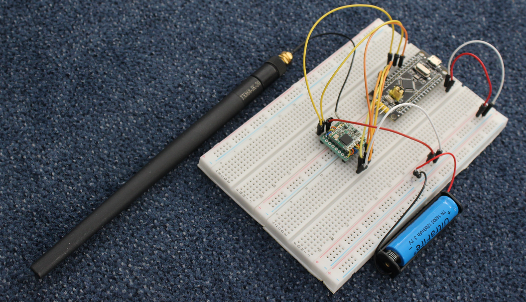
Today I added my project for a LoRa node based on an STM32F103c and an RFM95 on github. The project can be compiled on the Arduino IDE. A word document is also published there. It is rather easy to adapt the project to any sensor. The software is based on the well known ttn_otaa example by Thomas Telkamp and Matthijs Kooijman.
4 Likes