Unfortunately, the solution does not work for me in 2025.
My Firmware V1.6.1. 19. Jan. 2024
https://www.dropbox.com/scl/fo/ztlw35a9xbkomu71u31im/AMnEamqoeB3aaTsYDfwFtUM/LoRaWAN%20End%20Node/LT-22222-L/Firmware?dl=0&rlkey=ojjcsw927eaow01dgooldq3nu&subfolder_nav_tracking=1
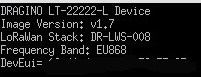
V1.7
-- 1.Upgrade LoRaWAN to DR-LWS-008 stack
1)Added multicast downlink functionality via server chirpstack.
2)Added downlink delay reset function, four bytes 0x04 FF xx xx, where xx xx is the number of seconds after receiving the command to reset.
-- 2.After adding a downlink control relay or DO port, save the status to FLASH immediately.Need to be used with AT+RODORET.
v1.6.3
-- 1.Optimize the interrupt trigger delay of AT+TRIG.
-- 2.Optimize serial port printing to prevent abnormal reset.
V1.6.2
-- 1.When AT+ATDC=0, the voltage and current alarms will continue to alarm.
V1.6.1
-- Fixed bug where current and voltage values could be incorrect due to TDC being too short.
V1.6.0
-- LoRaWAN Stack update to DR-LWS-007
-- Add AS923-2 band , AS923-4 band and MA869 band3.
-- Added AT+RODORET command
-- Use downlink type 02, 03, 05, A9 to change the status of RO DO, and the node will send the uplink immediately after the status is completed.
--Downlink type 05, A9 timeout adds 4 bytes of control
--Add AT+DECRYPT command
--Add AT+ GETSENSORVALUE command
--Add AT + DISFCNTCHECK command
--Add AT+DISMACANS command
--Add AT+RPL=5 command
v1.5.7
* OTAA RX2DR is set to 0 by default now for EU868
Image v1.5.7:
-- Compatible with 128K flash version ST chip
--Add AS923-2 band
Image v1.5.6:
--The RX2DR of EU868 frequency before entering the network was changed from 3 to 0.
--MCP3425 changed the material, and the software is compatible with the MCP3425 of two materials.
--Repair the sum value of the voltage and current acquisition definition is too small, causing the measured value to exceed half of the range Will overflow.
Image v1.5.4:
-- Upgrade LoRaWAN to DR-LWS-005 stack (http://www.dragino.com/downloads/downloads/LoRa_End_Node/DR-LWS/changelog)
-- Remove mod7
-- Change the implement of command AT+TRIG
Image v1.5.3:
-- Fix ADC sampling jitter bug
Image v1.5.2:
-- Fix DI1 and DI2 payload order
-- MOD1 can be used together with Interrupt mode now. If MOD1 want to use Interrupt mode, need to configure AT+TRIG first.
-- Send Interrupt packet first and then normal packet.
-- Interrupt can support rising and falling edge (only for MOD1, because other MOD use DI for counting).
----AT+TRIG=2,50,1 If there is a rising or falling signal >50ms on DI1. trigger Interrupt
----AT+TRIG=2,50,2 If there is a rising or falling signal >50ms on DI2. trigger Interrupt
Image v1.5.0
-- Add MOD6 , Similiar as MOD2, but the device will uplink on every interrupt.
Image v1.4.2
Ø Update LoRaWAN stack to DR-LWS-003 (http://www.dragino.com/downloads/index.php?dir=LoRa_End_Node/DR-LWS/&file=changelog )
Ø Fix DO / Relay state lose after reboot. Now After reboot, the DO/Relay will keep the same state as before.
Image v1.4.1
Ø Fix watchdog bug. This bug cause some devices will un-stop reboot with the v1.4 firmware.
Image v1.4
Ø Add hardware support for LT-22222-L
Ø Update LoRaWAN stack to DR-LWS-002
Ø Change to Class C by default
Ø Add Software Watchdog
Ø Re-construct Payload format, use the new decoder for v1.4.
Ø Add Downlink command to pre-set count number
Ø First bug for endless loop when TDC is too small
Image v1.3
Ø Add clear counting feature via Downlink
Ø Improve Downlink type code 0x03 to support control RO1 or RO2 separately.
Ø Add Downlink type code 0x05
Ø Add Downlink type code 0x07
Image v1.2
Ø Add counting feature
Image v1.1
Ø Voltage and Current reserve three decimal, previous is two
Ø Can use any Fport for downlink
Ø Add AT+CFG to print all settings
Ø Fix current and voltage glith bug
My new firmware V1.7 23. Sept. 2025