That was just an theoretical calculation. At that time, I was not aware that also the number of transmissions are regulated at TTN, thats now my biggest problem
thank you for that hint! I will check again the regulation!
You are right, I dont need the seperators in the end. I will recalculate it and change my code to SF7 125kHz. Lets see if I can stay into the borders of EU regulation “Worst” case for me would be to set up an own Gateway.
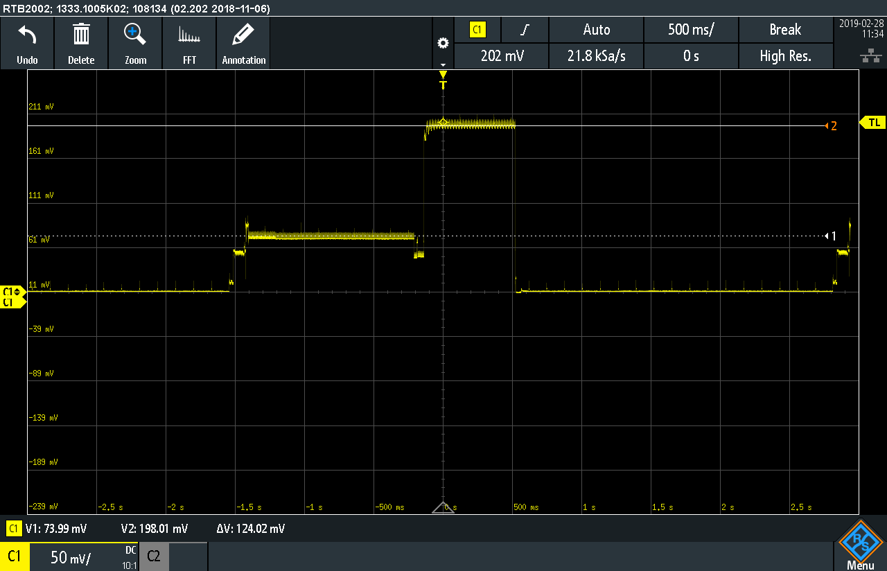
Okay, besides the talk about the frequency of sending my data, the problem with the ESP32 Board is still not solved. I measured again, because I found out, that I forgot to measure with the oszi against ground… it is looking like this now:
The time with the voltage of 198.01mV over 720ms is representing the time the LoRa module is on. Why is this not equal to the time on air/sending time? I am only switching it on for sending and turning it of after it.
“Bitrate” R_bit=SF* BW/2^SF *CR
"BW=125 kHz,SF=7,CR= 4/5
R_bit=5468,75Bits/s
"Bytes to transmit (only data)=12=96 Bits
(96 Bits)/(5468,75 Bits/s)=17,55 ms
Time to transmit the data would be 17,55 ms and the Board is on high power for over 700ms, even I am only sending which these 4 lines:
“Packet transmission time = Packet size / Bit rate”
At those parameters, time on air for an 12 byte packet would be around 40mS.
You also appear to be using a point to point LoRa library, and this being a TTN forum readers might not have much experience of that library, why would they really.
Can you explain it some more? I dont know what you trying to say here.
Where did you calculate this? I used a excel sheet available here in the forum for the 17ms.
You are right, I wanted to start with the point to point. If this is running (and I get the power consuption and number of transmissions down ) I will do the next step and try to unse TTN
For LoRaWan Class A, downlinks are only sent after uplinks. After sending, a node need to listen to see if there is a downlink packet sent. This happens during the RX1 or RX2 window (depending on the frequency plan / channel).
So it would make sense to me to wait for the receive window is over before going to sleep…
Okay, got it. Thank you.
Is it possible, that the LoRa module is by standard in the LoRaWAN Class A? So the chip is thinking, that its sending to a network? Cant figure it out why these times are not the same or even in the same area… but the 700ms is to huge!
I dont have access to the Semtech LoRa Forum and to the tools. I calculted with some more free calculators for LoRa and returning me the ~17ms is correct…
No, your missunderstanding the difference between what your trying to configure, point to point LoRa, and LoRaWAN.
Tell a LoRa device to send a packet and it does just that, and that only, it sends a packet. When its finished sending the packet it turns the transmitter off. It does not attempt any clever stuff like listening for replies. If you want to listen for a reply (like you might in LoRaWAN) you have to specifically configure the LoRa device to flip to being a receiver.
If you think the LoRa device is transmitting longer than you think it should be, you might want to raise the issue with the author of the library you are using.
As an aside, i notice you are using pins 34 and 35 as RX and TX. Note that those pins are input only. While it works now for an RX only operation, the TX on Pin 35 will never work should you try to transmit out of Serial2.
Thank you again for your explanation. I was just looking for a reason of the behavoir of the board - thats why i made the “default mode suggestion”.
I will try to contact the author of the library I am using with this issue, thats a good idea.