Full Arduino Mini LoraWAN below 1uA Sleep Mode

Its not difficult to modify a Pro Mini to get the sleep current down to 0.5uA, you remove the regulator and some resistors.

But then you have the issue of powering it.

AA Alkalines are not a good choice in my view, when new they are arounf 1.55V so you cannot use 3 since 4.65V is too much for the RFM95 without a regulator. AAs for around half their life are 1.2V, so 2 would give you 2.4V or lower, which can be an issue for some sensors.

As for needing to get as low as 0.5uA ?

Well at 0.5uA sleep current, assuming the board was only in sleep the battery would in theory last 639 years. At 25uA sleep current (which might sound a awful lot) the battery would last 13 years. The shelf life of the battery, due to self discharge issues, will be around 5 years. So there will be no practical differance in battery life between 0.5uA sleep and 25uA.

3 Likes

I am using LiFePo4 batteries, they are relatively stable around 3.2v for most of their capacity (when they reach 3v, I have typically a week to swap them before they drop under 2.7v)

Yep, the AA LiFePo4 are almost ideal, safer than your average LiPo incendiary too.

3 x AA Alkalines is fine, and they are cheap at places like Ikea. Just use them with a LDO regulator with a low IQ such as MCP1700. With one of them you can get sleep current to just under 2uA.

I like the idea to use the LiFePo4 battery, but is expensive and hard to find.
MCP1700 regulator is great but I like the challenge to use 2 x AA Alkalines, for some projects works perfectly.

https://www.aliexpress.com/item/4pcs-Soshine-3-2V-700mAh-AA-Battery-14500-LiFePO4-Rechargeable-Battery-Portable-Battery-Storage-Box-Case/32810015640.html

https://www.aliexpress.com/store/product/2pcs-Soshine-1800mAh-3-2V-LiFePO4-Battery-18650-Rechargeable-Battery-with-Protected-PCB-Portable-Battery-Storage/506629_32818927889.html

2 Likes

So I built one of Charles Hallard’s PCB’s in April of 2018, that is 50 weeks ago. I received a batch of 3.3v LiFePO4 batteries, 18650 size and I clipped one into the battery holder of the PCB, the voltage was 3.3v.
This has woken from deep sleep 96 times per day to report environmental data from a shelf in my kitchen and this is how it looks today:
Hallard_April_2019

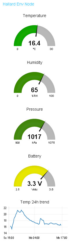
Operating from a LiFePO4 battery without any regulation is perfect IMO, perhaps I could have topped this cell off to 3.6 or 3.7v which I am reliably advised will not fuse the Arduino or the RFM95 but I didn’t and it still works very well.

If you are considering LiFePO4 then look carefully for a charger that can sympathetically charge these cells (they are different to LiPo !). Our in-house guru @BoRRoZ is testing a super good value bench power supply which would do the job nicely and lots more…

HTH?
G

1 Like

Right…

I started late for the game, so these are mine after 90 days:
35

I am using the 700mAh batteries @bluejedi is highlighting and poll a BME280 every 5 mins (288 times / day):

56

10

I threw bulles-minilora-01 outside mid-January to see how the battery reacts in colder temperature. It is now in the garden shed, that’s why it oscillates that much between night and day!

I can’t beat Garry on the duration, but hopefully with a relatively low capacity battery have a good idea on the actual power usage vs calculated one…

4 Likes

I use this for charging. It has an option for charging LiFePO4.
Smallest charge current is 500mA (unfortunately).

Normal charge current for my Soshine LiFePO4 cells is 300mA.
(Fast: charge 600mA for 14500 and 1.5A for 18650 cells)

https://www.aliexpress.com/item/LiitoKala-Lii-402-18650-Battery-Charger-For-26650-16340-RCR123-14500-LiFePO4-1-2V-Ni-MH/32818122465.html

1 Like

Ma Radio-Controlled car chargers are handling LiFePO4…
… but most of the time I am using my lab power supply – in particular for single cell, you don’t have to care bout balancing, …

Another (good) option for charging LiFePO4 batteries is ‘FOLOMOV-A4’, I use it to charge all Soshine 700mAh batteries for my nodes. The charger can be purchased here.

http://www.folomov.com/en/content/?125.html

1 Like

I have one of these solar chargers on a deep-sleeping ESP8266 in my garden shed which wakes to trigger my house alarm if needed.
charger

It is connected to a large solar panel and set to the panel’s MPPT (quoted on the panel) and tops off a 3.3v LiFeSO4 cell. If used on a low power node such as we talk about here then this is a stand-alone deployed for life device, even with a relatively small solar panel or not ideal conditions. The low level of power consumed makes the charge regime less of an issue. The boards are customised per the battery chemistry (discrete components on the pcb) so contact the seller to get the correct version.

G

Most of the (solar) chargers I have seen are LiPo chargers, and I don’t want to go to LiPo as it would require an LDO which will take some current…
A LiFeSO4 version would indeed be nice

I note from the specification;

“For lithium polymer batteries the under-voltage threshold is 3V”

Which is a lot better\safer than the normal so called ‘protection circuits’ that cut off at a miserable 2.4V.

1 Like

Hello,
Can you share your sleep configuration allowing to reach 1.3uA ? I’m stuck on higher consumption and I assume it comes from some pin settings around the RFM95 module.
Paul

If you search for posts by GryKyo on this thread I share lots of links (2-4months ago) to Charles Hallard’s resources. I take no credit as the work is mostly all his. You do need to use a soldering iron to remove the power LED and volage regulator from your Arduino board. This allows you to power the node directly from a LiFePO4 cell unregulated and without all the minute but inescapable losses of these components. Also (from my memory - be aware!) your code should as part of the deep sleep function call, set the Atmega 328 into it’s lowest power configuration. There is lots on the internet here but I am pretty sure that if you find Charles’ shared arduino sketches the appropriate setup is included.

HTH,
G

2 Likes

And the higher consumption is ?

I can’t reach 1.3µA either, I get at most 0.7µA…

:roll_eyes:

1 Like

“Allows to power” yes, but this thread is about ultra low power (titled “… below 1uA Sleep Mode”). Keeping the LED operational and keeping the voltage regulator in place will still eat current from your power budget unnecessarily. The power LED being the most worse (in mA range), but the voltage regulator will also draw quescent/leakage current which can easily take 6 uA up to tens of uA (depending on the type of regulator used).

Thank you for this answer, to be more precise my question is about the RFM95 module not the arduino part. this is the one consuming the uA I’m trying to save.

Please share when you find it. :slightly_smiling_face: