I already done it you need to declare os_getBattLevel() function in your sketch (like os_getDevEui()) and provide battery level according to LoRaWAN specification. Here my example but you need to adapt
/* ======================================================================
Function: os_getBattLevel
Purpose : callback for LMIC stack to know battery level
Input   : -
Output  : VBAT byte in LoRaWAN format
          MCMD_DEVS_BATT_MIN    = 0x01 // min battery value
          MCMD_DEVS_BATT_MAX    = 0xFE // max battery value
          MCMD_DEVS_BATT_NOINFO = 0xFF // unknown battery level
Comments: once fired this interrupt disable itself
====================================================================== */
u1_t os_getBattLevel(void)
{
  // remap VCC betwenn 2.5V and 3.6V to 0x01 => 0xFE
  // This is totally my choice, may be adjusted depending on device
  u1_t vbat = (uint8_t) map(ulpn.VBatAverage(), 2500, 3600, MCMD_DEVS_BATT_MIN, MCMD_DEVS_BATT_MAX);

  #if DEBUG > 1
  DebugF("os_getBattLevel(");
  Debug(ulpn.VBatAverage());
  DebugF(")=");
  Debugln(vbat);
  #endif
  return (vbat);
};
And then comment the existing definition in lmic.c of lmic library
Thanks @Charles, that’s pretty much what I’ve tried this week-end.
So far I don’t see the battery information in the LoRa frame - that’s where I need to check if and how the platform (here Live Objects, from Orange) is handling this data.
I know it’s working woth other professional devices (eg. a field test device from Adeunis) but I don’t know from where is taken the information (LoRa metadata? decoded from the payload?).
I implemented a field tester on cayenne for a customer, as far as I remember the battery level is send by the tester in the Payload (may be also on LoraFrame)
To see this in TTN metadata (or elsewhere) we need to ask @johan if it’s implemented.
Hi @Charles
have arrived, your cards ordered on PCBs.io, and I have already made a sensor successfully,
only with Arduino Pro Mini, RFM95 and antenna, without LEDs and other accessory components.
I want to implement the battery reading, via resistive divider on the Analogic A1 input (A0 already used), I have a doubt.
The sample scketch I found, requires the instruction analogReference (INTERNAL)
but in your pcb, input A0 is used connected to the RESET pin of RFM95,
can the analogReference () command create problems with the operation of the sensor ?
@Batigolle
What type of battery you will put? Lipo? If so you’re correct you need a voltage divider to read battery but I strongly suggest to use one that can be disabled to avoid current draw (see this one)
You can use another analog pin, A0 is using as digital I/O in this lora node so analog config will not hurt A0 pin.
I don’t know the sketch you’re using and what it’s doing with analog, so it’s difficult to answer.
@Charles,
My battery model it’s 18650 Li-Ion 3,7V 3000mAh
I use a voltage divider with two resistors 1M and 470K and capacitor 100nF in parallel
Very interesting your Battery-Voltage-Measure, I will consider it for the final product
I will try to replicate your circuit with normal components, I can not solder the SMDs
I’m using a basic sketch, with lowpower,
I’ll have to add an accelerometer, I’m building the step-y-step sketch
To read the battery, use the A1 pin with the command analogReference (INTERNAL).
I had the doubt if this command, which sets the maximum level of analogue pins, to 1.1 Volt, can affect the operation of the RFM95 module that uses the A0 pin
Yesterday I did some tests, it seems to work without problems
For the moment …
but the next step, I remove the regulator and the LED, to check how much the consumption decreases
Are there problems to remove the regulator ?
UPDATE
I read the old posts and there is a lot of confusion about removing the regulator …
I found three options
use the common Li-on rechargeable batteries, which have a voltage of 4.6V when they are fully charged,
removing the regulator, someone says that it works … but it is advised not to do it!
use a DC DC Converter Board Power Module, consumes a little more than the original controller, but allows you to take advantage of the use battery drop up to 1.8V
use lithium-thionyl chloride (Li-SOCl2) 3.6volt batteries, whose charge voltage does not exceed 3.6V
I already bought the batteries (Li-on),
I think that for the moment, I will take off only the Led
On a side note: I wish I had version 1.3 of the WeMos adapter board because My OLED display has the 3.3Vcc and GND reversed. I discovered this via the standard “magic-smoke release” procedure. After that smelly detour, I made an adapter for the second OLED display, (now operational on the target board), but I hope to manually modify the v1.2 WeMos adapter board itself to reverse the power leads, as is so easily done on version 1.1 of the Mini-Lora board. So thank-you for that. I think I will also order Version 1.3 of your WeMos adapter board before I build any more gateways!
Question: What does “pb” mean in the silkscreen sentence “Cut Wire if you put D1 to avoid LED pb”?
Question: Why does JP4/D1 only feed power to the first pixel,and not to the second one, which is always fed by 5V regardless of the configuration of JP4?
@BowElectric
Thanks for your head up and I apologize for magic smoke, that is usually why I’m trying to put connector name on silkscreen
Anyway for your 1st question, WS2812 is powered by 5V and clock signal is 3.3V (from GPIO Pin) so in rare case, 3.3V could not be suffisant do drive the WS2812. So I placed a diode between 5V and VCC of the WS2812, powering WS2812 diode with 5V-0.6V => 4.4V. See here for detail.
So you have 2 options when using this board, first don’t put D1 and let JP4 “as is”
then if you don’t have any led issue and led works as is (always worked on my side) so no need to do anything else.
led is not working as expected, solder D1 and cut wire of JP5 to power WS2812 with 4.4V
Question 2 because if 1st Led is powered by 4.4V, it output (DO) to the 2nd WS2812 Led will be 4.4V so no problem to drive 5V Led and all others LED will be driven by 5V output of the previous one
Now that is a battery! The sort of thing you can have in a device you can hold (and be able to see/read) or am I just showing my old age again? I’ve happy memories of my gran warming all of her cycle lamp batteries by the fire to extend their lives.
Your gran had a freezer? “Now there’s posh” as they say here in Wales. Reminiscing, she used to say “don’t leave the electric light ‘burning’” where burning would be an old gas/oil reference. She only had electricity wired downstairs – and this was London in the late 1950’s. Outside toilet too. Spinning off topic as usual …

 about removing the regulator …
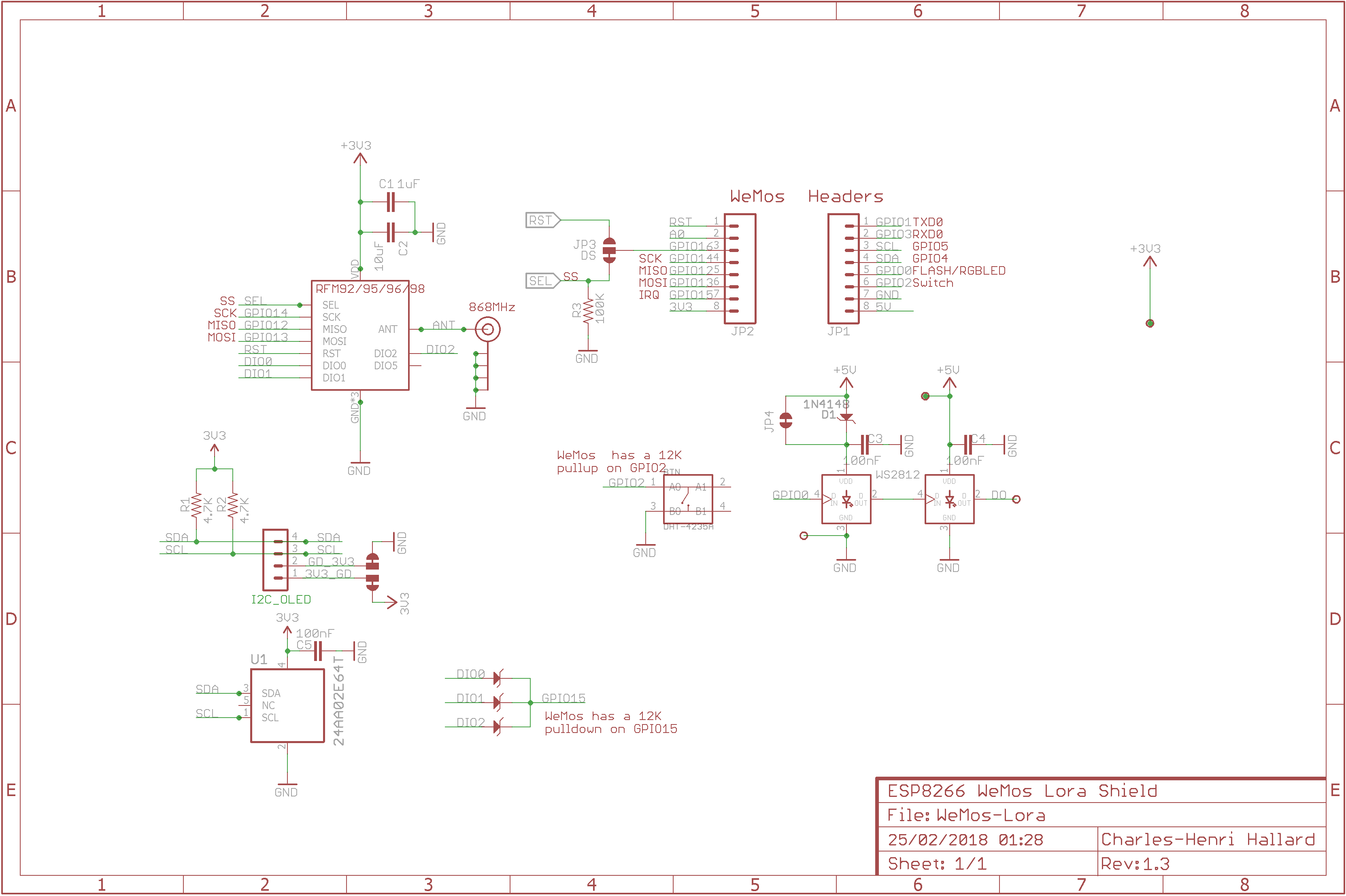