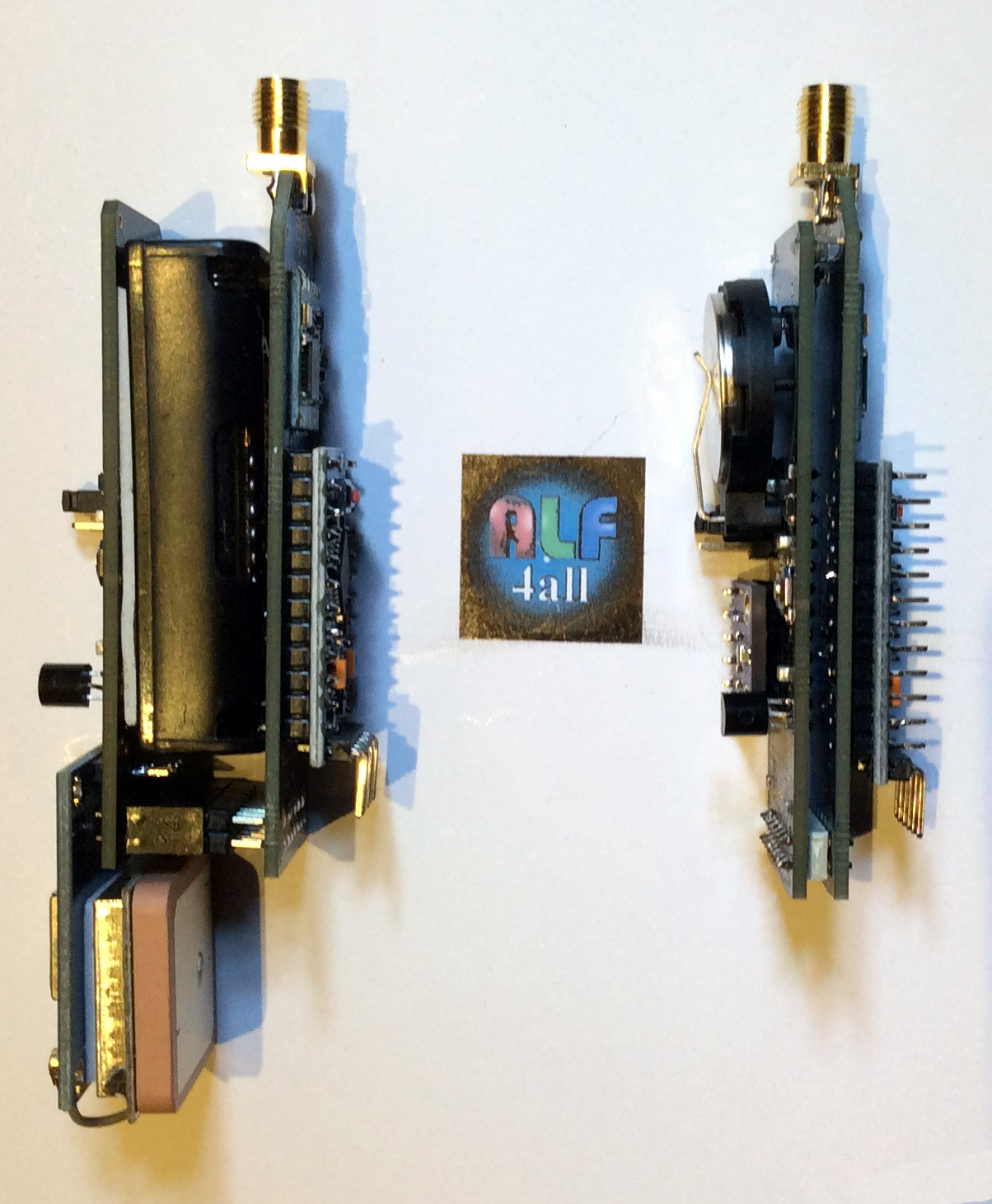
My iot_sandwiches: Left the fat_sandwich with the GY-GPS6MV2 module and powered with 2xAAA. Right the thin_sandwich with the BME280 and DS18B20, powered with a CR2032.
Both are using the TPS61291, TPL5111 and/or TPS22860 combination, Let’s consuming the whole system only 35nA (yes, nanoAmps, in sleep/dead mode).
A second version (same formfactor) with the BQ25570 harvester (for all kind of energy harvesting) is in the design fase.
sorry, but I’m still new to LoRa subject, rfm95w accepts to work in c class mode, so would not it just be software modifications? or rfm95 does not accept class c? ignore the question of power and battery
this specific arduino mini with a ‘tuned’ bootloader works for lorawan class A.
TTN doesn’t offer class C (always ON nodes) at this moment, that changes when V3 is operational.
there are only a few class C modules/nodes available yet … this will change soon
First I thought, what class is supported, depends on the gateway and/or server. You can program your node/device in that way that it’s support all tree classes. But class C: “is many times more energy consuming than Class A devices”.
If you don’t use the DONE signal to the system-timer TPL5111 in my node/device, it stays always powered on and can handle class C. So “Of cource not” is not the case.
only partly through… the LoRaWAN stack IN the the device determs what classes.
this topic is about Charles CH2i design of a lowpower node… not your node/device
OK, stacks in devices are not always accessible to the user (could also be hardware and/or firmware), but is Charle’s consept also not build with the ATmega328P and RFM95W?
That’s not the best possible decoupling capacitor. Can substitute with those of NP0, X7R or X5R ones that are better in terms of tolerance across operating temperature range which are plenty to choose from like these.
I have a bunch of NCR18650B panasonic batteries. I’m having a hard time understanding the datasheets and characteristic of these batteries, it says 3.6V “nominal voltage” but then theres a lot of talk about 4.2V everywhere? Will they be fine or toast the lorachip?
They are not directly interchangeable but both can be made to work. The BME280 connects via I2C and the DS18B20 is a 1-Wire technology. You will require different software libraries and the wiring to the pins will also change. I2C has 4 wires, +ve, 0V, Clock and Data with pull-up resistors on the Clock and Data lines. 1-Wire is a 3 wire system with a pull-up resistor on the data line.
Ok, I have been using both BME280 and DS18B20 on r-pi & nodemcu, but maybe the arduino isn’t as configurable as these two?
I was hoping one of the SDA/SCL pins could be used for 1-wire data line?
Is it possible to use one of the led-pins for the data wire? D5/D6/D9? (Of course then not using the led).
That would be even better, ultimate solution would be both BME280 + 1wire/DS18B20 at the same time, but then maybe the flash wont be enough for both libraries at the same time?
Just following this example, but changing pin 3 for 5,6 or 9?
Does anyone have a small example of just how to handle the sleep with 5110, I’m confused after reading code examples here. A lot of them seem to use “internal” watchdog with 8sec-stuff?
Question 1: Why does people use internal watchdog when we have the 5110?
Question 2:
I thought that the 5110 would completely shut down everything as in the adafruit example, but it seems like Hallard did it a bit different.
Why doesn’t we just cut the power entirely and wake up doing a full setup() + loop()? I don’t say its wrong, I’m just curious about the benefit doing it this way instead…
Question 3:
As I understand it I need to do something like:
Setup: Tell arduino to wake up when signalled on A2
End of loop: Signal 5110 done and tell arduino to sleep
Are you guys using this code? Or something like it?
I guess I need to modify the loop() to also signal 5110 done pin?
Sorry for the “basic” questions, but if you don’t ask, you don’t learn
The internal watchdog is ‘internal’ to ATmega processors, its included, its free, needs no additional components.
If you remove the power from the ATmega, you loose all the varaibles and status. A processor woken from sleep can be running where it left off in a few mS, whereas with a fresh restart every time it can take 1.5 seconds or so of full running, more if you need to run through the join process again. This can use a lot of power.
Q1. There is no good reason to use the watchdog if you have external interrupt available
Q2. As already said, if you cut the power you loose the state, so you would have to store it “somewhere” (e.g. FRAM) to restore it. It is something I am doing on boards where I can’t get the power down to an acceptable level in sleep mode, but it is a pain.
Q3. If you are using @Charles design you can’t use @rocketscream low power library as the 5110 is not wired to an external interrupt (you need to use pin change interrupt)