I’ll also be interested in the surge protection methods. I have the RPi Plugged into a surge protector but also a network module I need to connect up too.
While I haven’t done anything yet with the jumper wires I noticed that now the antenna is outside (and I’ve also moved the gateway to another location f the garage where as before it was close by to the power in) while the signal seems worse than I used to get (With the new antenna I got) I now get to a lower RSSI before actually getting no response so it seems height has improved it.
I’ll likely be getting the ~£20 one I linked and mounting it up high and report how it goes .I’ll also see about getting a PCB for the jumper wires instead.
I use a “standard” gateway to calibrate a range of antenna types and sizes. I use the IEEE recommended method for RF testing and calibration that uses a standard dipole closely matched to the frequency. I have an RPi + Coredump backplane + IMST iC880a gateway with the u.fl–SMA pigtail and then a purchased high-quality 1m SMA RG58 coax cable to a Taoglas TI.08.A.0111 antennae purchased in UK from Digikey and positioned vertically. Devices then start in default configuration at a fixed distance of 3m. At this range the TTN core generally reports receiving uplinks with an RSSI of about -22 dBm to -26 dBm. Then I know that all the basics are working correctly and I can start changing one thing - cable, antenna, position, distance, etc. - at a time. The Taoglas antenna datasheets are good as they provide a lot of detail. I would not purchase an antenna that does not provide this kind of detail. LoRaWAN is very low power and so the transmission line, antenna and antenna position are critical. Be aware that LoRaWAN ADR will step in to reduce the device TX power if the gateway RSSI is very strong. DiY antenna work is good for devices but I always use high-quality purchased transmission line and antennae for gateways.
LPWAN coverage range on radio propagation – NB-IoT, Weightless, LoRaWAN & SIGFOX
If you are planning to deploy your own LPWA network then you’ll need to understand a few things about RF signal propagation, run a few models and then conduct a few tests in the real world. In this article, we are going to explore what is involved so fasten your seat belts and let’s go…
First off, remember the maxim, “keep it simple”. We are going to progress through a series of steps and it will quickly become obvious that it makes sense to approach these in sequence.
Step one – Line of sight
It seems obvious, doesn’t it? If you cannot see the location of the end device from the location of the base station then the base station cannot ‘see’ the end device. Buildings that you cannot see with your eyes, because, for example, they are in a valley or behind a mountain, cannot be covered with a base station antenna, at least not reliably, from that height. This is the first stage of any physical network planning process and it is intuitive. The obvious way to maximise coverage is to choose locations where you are able to see a large number of the places where your end devices will be located and this typically means that a base station will be mounted as high as possible. This much is obvious but it makes sense to take this first simple step in your network planning. What is stage two? Modelling…
Step two – Radio Propagation by Excel Sheet
If you have a list of possible base station locations then you can use a radio propagation model to plan the possible coverage from each base station. In the basic step, you use an Excel Sheet and a common radio propagation formula to calculate an estimated coverage range. Each base station antenna coverage will be shown by a circle. The picture as below shows the planning of an LPWAN with six LPWAN base stations at the factory plant of Volkswagen in Wolfsburg.
Read more: http://www.gsm-modem.de/M2M/iot-university/lpwan-coverage-range/
I’ve gone for the antenna that I linked to on eBay and got the cable and connectors today. I’ll be fitting it tomorrow about 21" above my Garage which is the highest I can put it and it’ll also be outside. I’ll report back once I’ve done it and done some testing.
Second update, Not sure if I should have done this as an edit or not but.
New antenna (From eBay) mounted about 1M Above the roof of our garage which is about the same height as our house and the highest I can get it. Gets a range of about 800 Meters, about double the distance but still far far off even 2KM. I have a few more tweaks I need to make (Possibly seeing about wiring the board better between the Pi and IMST Board) and one of the connectors. One thing I notice is while long range is much better short range is worse so I think one of the connectors on it needs replacing.
I ended up building my own J-pole style collinear antenna.
The setup seems to work pretty well.
It is based on this design. http://www.qsl.net/n9zia/wireless/pics/915-jpole.png
Easy to fabricate using some stiff copper (or even steel) wire and some PVC water pipe.
I did adjust the dimensions slightly for 930MhZ.
I am based in an outer suburban area of Melbourne, Australia on the side of a very slight hill.
The antenna is mounted on my roof top at a height of about 5m from the ground.
I did a bit of drive testing around the area to test the range.
I can get typically up to about 2.5km with 1km range quite comfortably.
This is with 2 way communications. Testing being don with a simple PC connected RAK8811 modem and a simple rubber duck style dipole antenna.
My best test so far has been at the top of a small nearby mountain range (10.6km away).
I think the radiation pattern from my antenna is not yet optimal. I think it might be radiating a bit too much energy skyward.
Because I ordered the wrong connector currently it’s not soldered on and has the centre pushed in and the shielding cable tied to the outside of it. I suspect when I get a new one which I can solder it’ll improve both long and short distance.
I need to do some tweaks and more range testing. (When I get the new connector I should also be able to cut about another 50-100CM of cable off). For range testing I’m planning on driving in a few other directions using the original antenna I got from Amazon. (While not great for gateway it works well for a node that can be stuck to the top of my car).
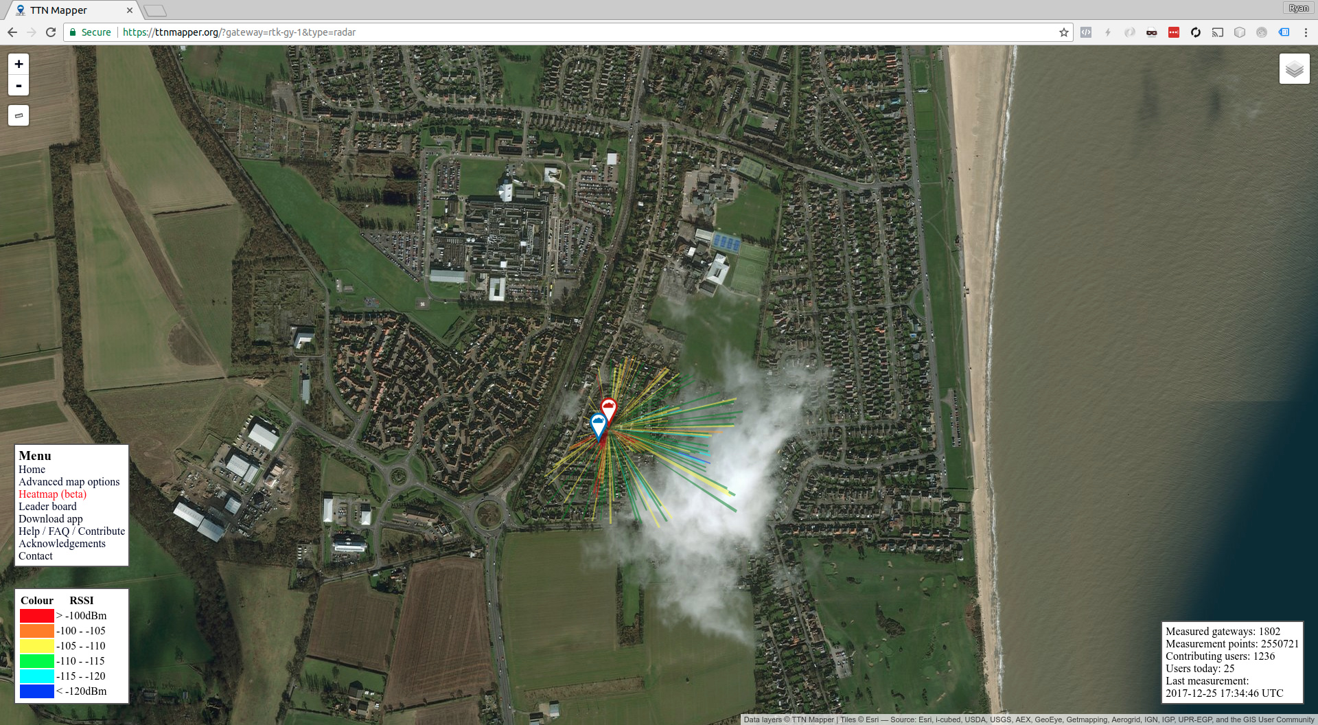
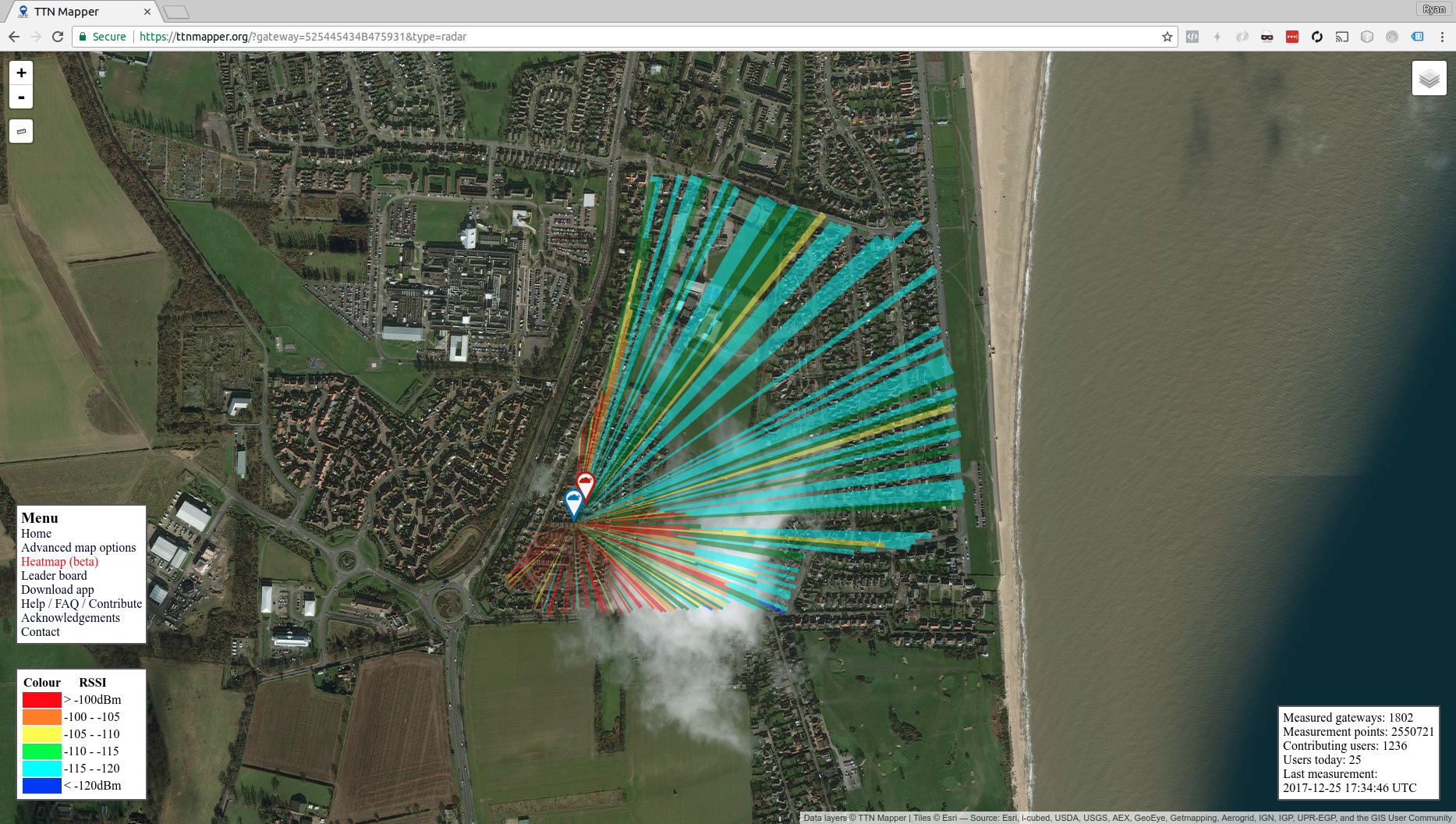
Here’s a current before and after image. (I changed software used hence the change of gateway ID).
I’m hoping with some more improvements I should get it to around 3KM Range which I deem acceptable as this would cover a majority of the town I live in. 6KM Would be ideal still however don’t believe I can go any higher.
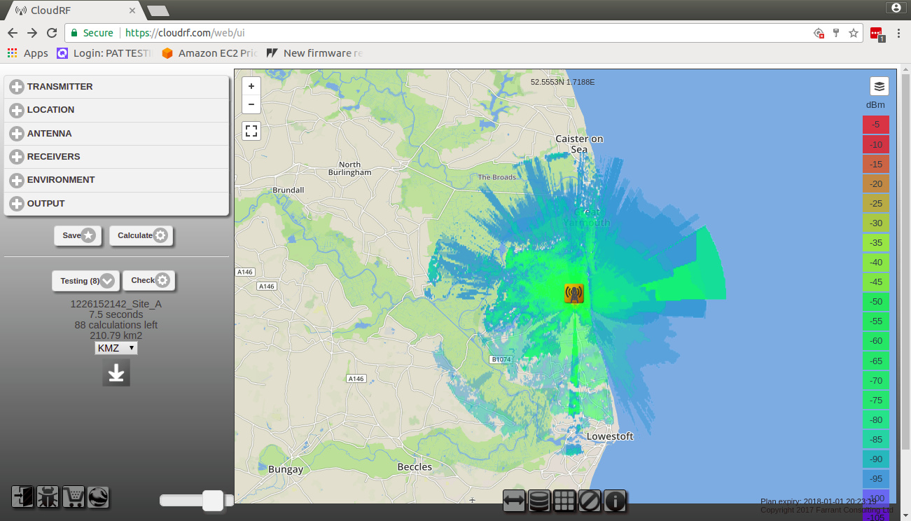
Propgartion simulation at this website is done using Radio Mobile. You can find more about this free propagation simulation sofware at: http://radiomobile.pe1mew.nl/
In case you hadn’t run into this yet:
"Similar to the situation with Radio Mobile there is no real documentation avaialable from the author. To cover this issue a website with documentation is available at http://radiomobileonline.pe1mew.nl "
I played with several different simulation tools end of 2016. You are right. All tools are not easy to use. How to use it will be a part of my new IoT / M2M Cookbook. I will explain it by a private LPWAN for the small village where I am born. Every reader will plan the network for the small village again. The lesson learned everybody will copy to its own network.
I got 3,5km using SF7. Unfortunately the surrounding terrain is a little higher than my house. The main problem are houses etc. Line of sight is nearly impossible. But for the place I’m ok with the range I get.
A mix of the new antenna, It being put up higher and other improvements have ment the range is much better. I’m still mapping it out however am now picking up signal from between 2-4KM, Much less than the 10-15 KM most devices claim but more acceptable in my view.