Nice find! And that also explains why the correction code might work just fine when waking up from code, rather than from an external interrupt, as then the maximum sleep time is so much smaller? (Often people need a loop to sleep repeatedly to achieve longer times.)
1 Like
I guess if you really sleep (that is: delay()), you would get the same behaviour as the IBM co-routine mechanism does not benefit from yield()…
The thing is in non-hardware sleep, you would just re-schedule a task, not slepping.
But we see that in the 5 min test the clocks are behaving better because we call os_getTime() more often.
As the overflow if about 71 minutes, we need to ensure we update at least twice in that timeframe, so if we update every 30 mins, we shoudl be good…
(again: to be tested…)
The code you quoted is essentially the basis for my code and it works as long as the total sleep time between sends does not exceed a certain limit. This limit is based on the explanations from @Amedee in the previous post. I will summarise my findings in a separate post now.
Ok, after doing more testing I think I got a pretty good and complete picture of what happens and how to avoid it.
Actually @Amedee hit the point brilliantly well by analysing the os_time counter and the os_getTime() function.
Sleeping the AVR works well if os_time is kept accurate, which can be achieved by calling os_getTime() regularly. As he explained, regularly means at least about every 30 minutes. More often is better.
Contrary to what I thought, calling os_runloop_once() does not update os_time whereas doing an actual send does. Hacking the times is also only neccesary if the tasks between the sleep does not exceed the time required for the duty cycle anyway (rarely, I guess).
The full procedure with updating time0_overflow_count and timer0_millis in atomic mode is not needed. The simple timer0_overflow_count hack with disabled interrupts (cli, sei) is sufficient but will make your millis() lag behind. Should not matter except for special cases.
If you put the AVR to sleep forever and wake it by interrupt, do not modify the time by more than 30 minutes afterwards regardless how long the sleep was. Better only add e.g. 1 minute which is sufficient for the duty cycle, do the os_getTime() and you are good. Adding e.g. 60 minutes at once will give you problems from time to time.
In short:
You can put the AVR to sleep as short or as long as you like.
You should add only limited time (minutes!) to timer0_overflow_count after sleep.
Always call os_getTime() after modifying timer0_overflow_count to get the os_time updated.
You do NOT need to call os_runloop_once() after waking as it does “not do anything helpful” at that time.
Many thanks to all of you helping find these nasty send delays and get this sorted out. This really is a forum with brilliant, knowledgeable and helpful people being around! 
Finally, here is a working example code sending every hour and sleeping in between:
/*******************************************************************************
 * Copyright (c) 2015 Thomas Telkamp and Matthijs Kooijman
 * Copyright (c) 2018 Terry Moore, MCCI
 *
 * Permission is hereby granted, free of charge, to anyone
 * obtaining a copy of this document and accompanying files,
 * to do whatever they want with them without any restriction,
 * including, but not limited to, copying, modification and redistribution.
 * NO WARRANTY OF ANY KIND IS PROVIDED.
 *
 * This example sends a valid LoRaWAN packet with payload "Hello,
 * world!", using frequency and encryption settings matching those of
 * the The Things Network.
 *
 * This uses OTAA (Over-the-air activation), where where a DevEUI and
 * application key is configured, which are used in an over-the-air
 * activation procedure where a DevAddr and session keys are
 * assigned/generated for use with all further communication.
 *
 * Note: LoRaWAN per sub-band duty-cycle limitation is enforced (1% in
 * g1, 0.1% in g2), but not the TTN fair usage policy (which is probably
 * violated by this sketch when left running for longer)!

 * To use this sketch, first register your application and device with
 * the things network, to set or generate an AppEUI, DevEUI and AppKey.
 * Multiple devices can use the same AppEUI, but each device has its own
 * DevEUI and AppKey.
 *
 * Do not forget to define the radio type correctly in
 * arduino-lmic/project_config/lmic_project_config.h or from your BOARDS.txt.
 *
 *******************************************************************************/

#include <lmic.h>
#include <hal/hal.h>
#include <SPI.h>
#include <LoraMessage.h>

#include "LowPower.h"
//#include <util/atomic.h> //Only needed for full version to update time

volatile boolean powerdown=false;

unsigned int Vbat;

// This EUI must be in little-endian format, so least-significant-byte
// first. When copying an EUI from ttnctl output, this means to reverse
// the bytes. For TTN issued EUIs the last bytes should be 0xD5, 0xB3,
// 0x70.
static const u1_t PROGMEM APPEUI[8] = { XXXX };
void os_getArtEui (u1_t* buf) {
  memcpy_P(buf, APPEUI, 8);
}

// This should also be in little endian format, see above.
static const u1_t PROGMEM DEVEUI[8] = { XXXX };
void os_getDevEui (u1_t* buf) {
  memcpy_P(buf, DEVEUI, 8);
}

// This key should be in big endian format (or, since it is not really a
// number but a block of memory, endianness does not really apply). In
// practice, a key taken from ttnctl can be copied as-is.
// The key shown here is the semtech default key.
static const u1_t PROGMEM APPKEY[16] = { XXXX };
void os_getDevKey (u1_t* buf) {
  memcpy_P(buf, APPKEY, 16);
}

static osjob_t sendjob;

#define TX_INTERVAL 3600           //seconds of sleep between sends
#define SLEEPCYLCES TX_INTERVAL/8  // calculate the number of sleepcycles (2s/8s) needed for the given TX_INTERVAL

// Pin mapping
const lmic_pinmap lmic_pins = {
  .nss = 10,
  .rxtx = LMIC_UNUSED_PIN,
  .rst = 4,
  .dio = {2, 3, LMIC_UNUSED_PIN},
};


void onEvent (ev_t ev) {
    Serial.print((unsigned long)(os_getTime()/ OSTICKS_PER_SEC));
    Serial.print(": ");
    switch(ev) {
        case EV_SCAN_TIMEOUT:
            Serial.println(F("EV_SCAN_TIMEOUT"));
            break;
        case EV_BEACON_FOUND:
            Serial.println(F("EV_BEACON_FOUND"));
            break;
        case EV_BEACON_MISSED:
            Serial.println(F("EV_BEACON_MISSED"));
            break;
        case EV_BEACON_TRACKED:
            Serial.println(F("EV_BEACON_TRACKED"));
            break;
        case EV_JOINING:
            Serial.println(F("EV_JOINING"));
            break;
        case EV_JOINED:
            Serial.println(F("EV_JOINED"));
            /*
            {
              u4_t netid = 0;
              devaddr_t devaddr = 0;
              u1_t nwkKey[16];
              u1_t artKey[16];
              LMIC_getSessionKeys(&netid, &devaddr, nwkKey, artKey);
              Serial.print("netid: ");
              Serial.println(netid, DEC);
              Serial.print("devaddr: ");
              Serial.println(devaddr, HEX);
              Serial.print("artKey: ");
              for (int i=0; i<sizeof(artKey); ++i) {
                Serial.print(artKey[i], HEX);
              }
              Serial.println("");
              Serial.print("nwkKey: ");
              for (int i=0; i<sizeof(nwkKey); ++i) {
                Serial.print(nwkKey[i], HEX);
              }
              Serial.println("");
            }
            */
            // Disable link check validation (automatically enabled
            // during join, but because slow data rates change max TX
            // size, we don't use it in this example.
            LMIC_setLinkCheckMode(0);
            break;
        /*
        || This event is defined but not used in the code. No
        || point in wasting codespace on it.
        ||
        || case EV_RFU1:
        ||     Serial.println(F("EV_RFU1"));
        ||     break;
        */
        case EV_JOIN_FAILED:
            Serial.println(F("EV_JOIN_FAILED"));
            break;
        case EV_REJOIN_FAILED:
            Serial.println(F("EV_REJOIN_FAILED"));
            break;

    case EV_TXCOMPLETE:

        Serial.println(F("EV_TXCOMPLETE (includes waiting for RX windows)"));

        if (LMIC.txrxFlags & TXRX_ACK)
        Serial.println(F("Received ack"));

        Serial.println(F("sent"));

      //send/receive cycle completed
      powerdown=true;
      break;

        case EV_LOST_TSYNC:
            Serial.println(F("EV_LOST_TSYNC"));
            break;
        case EV_RESET:
            Serial.println(F("EV_RESET"));
            break;
        case EV_RXCOMPLETE:
            // data received in ping slot
            Serial.println(F("EV_RXCOMPLETE"));
            break;
        case EV_LINK_DEAD:
            Serial.println(F("EV_LINK_DEAD"));
            break;
        case EV_LINK_ALIVE:
            Serial.println(F("EV_LINK_ALIVE"));
            break;
        /*
        || This event is defined but not used in the code. No
        || point in wasting codespace on it.
        ||
        || case EV_SCAN_FOUND:
        ||    Serial.println(F("EV_SCAN_FOUND"));
        ||    break;
        */
        case EV_TXSTART:
            Serial.println(F("EV_TXSTART"));
            break;
        default:
            Serial.print(F("Unknown event: "));
            Serial.println((unsigned) ev);
            break;
    }
}

void do_send(osjob_t* j) {

  // Check if there is not a current TX/RX job running
  if (LMIC.opmode & OP_TXRXPEND) {
    Serial.println(F("OP_TXRXPEND, not sending"));
  } else {

    //Prepare data
    LoraMessage message;

    message.addUint16(Vbat);

    // Prepare upstream data transmission at the next possible time.

    Serial.print((unsigned long)(os_getTime()/ OSTICKS_PER_SEC));
    Serial.print(": ");
    Serial.println(F("Queue packet"));

    LMIC_setTxData2(1, message.getBytes(), message.getLength(), 0);

  }
  // Next TX is scheduled after TX_COMPLETE event.
}


void setup() {

  Serial.begin(115200);
  Serial.println(F("Starting"));

  // LMIC init
  os_init();

  // Reset the MAC state. Session and pending data transfers will be discarded.
  LMIC_reset();
  LMIC_setClockError(MAX_CLOCK_ERROR * 1 / 100);  //Relax RX timing window

  // Start job (sending automatically starts OTAA too)
  measure();  //Do a first measurement at startup
  powerdown=false;
  os_setTimedCallback(&sendjob, os_getTime() + ms2osticks(10), do_send);
}

void loop() {

  extern volatile unsigned long timer0_overflow_count;
  os_runloop_once();  //check send status

  if (powerdown) {

    Serial.println(F("go to sleep ... "));
    Serial.flush();

    for (int i=0; i<SLEEPCYLCES; i++) {
      // Enter power down state for 8 s with ADC and BOD module disabled
      LowPower.powerDown(SLEEP_8S, ADC_OFF, BOD_OFF);
      //LowPower.powerDown(SLEEP_2S, ADC_OFF, BOD_OFF);

      //Give the AVR back the slept time back (simple version)
      cli();
      timer0_overflow_count += 8 * 64 * clockCyclesPerMicrosecond(); //give back 60 seconds of sleep
      sei();

      /*
      //Give the AVR back the sleep time; full version with millis() update
      //Needs '#include <util/atomic.h>'
      unsigned long slept=8*1000;
      ATOMIC_BLOCK(ATOMIC_RESTORESTATE) {
        extern volatile unsigned long timer0_millis;
        extern volatile unsigned long timer0_overflow_count;
        timer0_millis += slept;
        // timer0 uses a /64 prescaler and overflows every 256 timer ticks
        timer0_overflow_count += microsecondsToClockCycles((uint32_t)slept * 1000) / (64 * 256);
      }
      */

      os_getTime();   //VERY IMPORTANT after sleep to update os_time and not cause txbeg and os_time out of sync which causes send delays with the RFM95 on and eating power

      //Do here whatever needs to be done after each of the sleepcycle (e.g. check for a condition to break for send or take measurements for mean values etc.)
    }

    //Instead of the for-loop, a SLEEP_FOREVER can be used with waking by interrupt (if defined)
    //LowPower.powerDown(SLEEP_FOREVER, ADC_OFF, BOD_OFF); //Also only add e.g. 1 minute after wake to time0_overflow_count if this is used
    //os_getTime();   //VERY IMPORTANT after sleep to update os_time and not cause txbeg and os_time out of sync which causes send delays with the RFM95 on and eating power

    Serial.begin(115200);
    Serial.println(F("... done sleeping"));

    powerdown=false;
    measure();  //get some data
    os_setTimedCallback(&sendjob, os_getTime() + ms2osticks(10), do_send);  //do a send
  }

} //loop


void measure() {
  //Assumes you have a voltage divider at A0. Preferrably one that does not drain battery, like this one:
  //https://jeelabs.org/2013/05/16/measuring-the-battery-without-draining-it/
  Vbat = analogRead(A0) / 1024.0 * 3300 * 2;  //Assuming you run on 3.3V
}
7 Likes
Hi, i tried your sleepmode and it worked perfectly.
But i have a question about the battery measuring. What numbers do you get for analogRead(A0)? I am trying to debuggin, thats why i need some numbers i can compare with.
It can be anything depending on your voltage divider and you reference voltage (1.1v is typically the only one usable on battery powered AVR unless you have a regulator)
i use a arduino pro mini and my circuit looks like this. I operate with 3.3 V. The only thing i changed in code was the Pin. And yes, i am using the 1.1 V
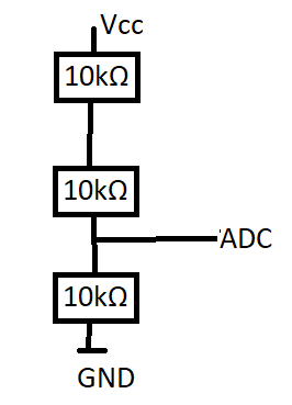
Hi, you should get values around 1024 with your setup on the arduino pro mini (3.3V*(10 kOhm/30 kOhm)*1024/1.1V) if VCC really is 3.3V and you use the 1.1V reference setting using analogReference (INTERNAL);.
If you keep the default, or analogReference (DEFAULT); external VCC (3.3V) reference, you should see about 340.
I typically use the default reference (VCC) as I usually drive the Arduinos by LiPo Battery with a regulator or with an upconverter from an AA-Battery to 3.3V which for my purposes gives me sufficiently precise 3.3V to get me something to measure the Battery (or solar cell voltages) against.
See http://www.gammon.com.au/adc for details on the ADC and reference voltages.
As Amedee says, if you use e.g. 4.1 V on VCC and use a regulator, you will see higher values, or in your case still 1024.
However, depending what your needs are, the 30 kOhms you have between VCC and GND might drain your battery (if you are running from battery, of course) unnecessarily as it will add another 100 uA of wasted amperage which sounds not like a lot but actually is compared to a bare sleeping Pro Mini (without LED and any sensors attached). If you have the Power-LED still connected (ca. 2 mA) , it does no longer matter.
Having said that, this is why I love the jeelabs-setup I mentioned in my code example. (https://jeelabs.org/2013/05/16/measuring-the-battery-without-draining-it/) using 2x 10 MOhm resistors (or anything below but the higher, the better, if you don’t have 10 MOhm resistors) and a 0.1 uF capacitor in parallel from PIN to GND a lot better than 10 kOhm Resistors.
This saves you a lot of power without degrading precision for just measuring the battery voltage.
I concur…
With a 1/3rd divider and 1.1V reference you will max out unless you feed less than 3.3V, and you will waste power.
Now…
… if you use a Atmel 328p (Pro Mini) you don’t really need all that, just read the voltage from the chip (see here)
1 Like
Very good remark! ![]()
Yes, if you want to measure VCC and power directly into the VCC Pin (not using the regulator, otherwise it is essentially pointless as it is “always” 3.3V).
No, if you want to measure VBAT or anything else like I wanted in my example.
1 Like
Good point as well, in my case I have no regulator, so VCC is my VBat ![]()
1 Like
yeah i get the same results as you mentioned.
When i use analogReference (INTERNAL); i get for Vbat=2178. But that cant be the Battery Status right? I know these questions might be dumb, but they help me to understand the entire process.
analogReference (INTERNAL); =>Vbat=6593, AnalogRead=1023
analogReference (DEFAULT); => Vbat=2178, AnalogRead =338
You should indeed try to understand what you are doing instead of applying random formulas…
You have a 1/3rd divider, so you will measure 1/3rd of your voltage at the pin, so you need to multiply the end result by 3…
You will measure that against a reference. Analog 0 being 0v and analog 1023 being Reference Voltage.
When you have INTERNAL (1.1V) and 1023, your voltage is 1023/1023 * 1.1 (ref) * 3 (divider) = 3.3v (or more as you are at the maximum)
When you have DEFAULT (3.3V assuming you have a 3.3V regulator) and 338, your voltage is: 338/1023 * 3.3 (ref) * 3 (divider) = 3.27v
So it looks to me pretty consistent if you try to measure 3.3v…
2 Likes
Now thats a explanation i can work with. Its hard to understand if everybody is trying different methods, with little pieces of explanations with different libraries and code examples. People with a lot of experience may understand and look at it as a easy thing, but newbees like me will just drown, so i have to poke with dumb question to get the full understanding  Good and very detailed instructions with step by step are hard to find.
Ty for your help