Okay. I will try to look into making the BPF filter and the antenna better while transmitting at lower power. The problem with this is I have very limited component selection because of the ultra low weight requirements.
This is very interesting. It would be also interesting to see what transmitting power and spreading factor they used. I suppose it’s there’s somewhere, I will look trough the website thoroughly later.
Well this is very, very interesting. Maybe this has been causing the range for my probes to be small before. When you loose range with lower SF but you increase the risk of the gateways not being able to catch the packet at all, the question of where is the sweet spot is coming to my mind. Because I don’t think the probe will ever be going slower than 25kph.
Most of the HAB community have the wire antenna vertical with a tin foil ground plane for local flights, not particularly directional at all. A guitar string quarter wave antenna with radials would be better.
There is considerable support available in creating a circumnavigating floater, often switching to APRS over the US and then back to normal LoRa - we get heads up on IRC that one is coming our way and tune in to help with tracking.
Given the patchy coverage in parts of the world for LoRaWAN, maybe you want to rethink your comms strategy.
Did you measure the loss through the band pass filter you currently have and the level of harmonics ?
The problem with making the antenna ‘better’ is that you need to reduce the power to compensate for the gain. If this is a directional antenna all you will achieve (over a standard vertical) is the exact same coverage\distance in one direction and reduced range in the other directions.
The one advantage of a directional antenna is that you get the same distance\coverage in one direction (but worse in others) using a lower transmit power, thus saving battery power.
Okay. Thank you. Having more than 700km of range with that is very impressive.
The wire I use is actually 1/4 wave. A guitar string is most times too thick and heavy for me. I’m considering using a ceramic chip antenna, as I do for the GPS receiver. The problem is that the probe is so small that the ground plane is only 30mm. Maybe I will deal with that with some radials.
Yes. I know that many people use APRS for this but for quite some time I’ve been trying to not use APRS. I don’t have a license for it yet. Also, we are thinking of having balloon kits available for the general public. There we would need it to be operating in the “free” band.
We are finishing backlogging functionality right now. This will enable us to have some limited data from parts of the flight where the balloon was not in covered area. This is simple. But we also plan working to develop the hardware and software for hive floater operation. This means that we could communicate trough multiple floaters from uncovered areas to covered areas.
Not really. I’m not sure whether I have immediate access to equipment to test this. These new designs were made during quarantine and while I consulted with an RF engineer, I didn’t have to actually test this yet. Can you do some tests like these with an SDR or do you need something more special (expensive).
I see. Because the plan is to work on hive communication between balloons, it would be best to actually have the signals being omnidirectional. The antenna gain is added to the transmitting power right?
The probe uses a small solar panel with weight of around 2 grams. This is enough to give 0.4W on a sunny day which is enough to transmit at full power. But of course, lower power consumption is never a bad thing.
Have you contacted the ukhas group? They have a lot of practical information and a really nice tracker map. Their website is at http://habhub.org/
They have a google groups mailing list, and an IRC channel with helpful people.
I myself wrote a kind of bridge between TTN and the habhub tracker site, that receives telemetry packets from TTN and forwards them to habhub for display on the map: https://revspace.nl/TTNHABBridge
Yes I know this. We use the Habhub tracker and predictor for our HAB launches.
Oh, I didn’t know that. I found it on the site now. I will try it.
This is really cool. I wanted to connect my floaters to Habhub myself but I gave up because I didn’t find anything like this back then. But now I’m using Tago IO and I’m really happy with it. It offers a very large degree of customization which is very useful. My dashboard looks like this. The thing I don’t like about Habhub is that the map is so dominant and it’s harder to clearly read all of the other data compared to a chart on Tago. We want to develop our own web interface for this purpose. It will be similar to the Tago dashboard but will have some custom stuff like a 3D globe view instead of a map. But instead of viewing one probe, you will be able to switch between different ones on a map, as you can on Habhub.
Appreciate that a tracker at altitude is capable of causing significant disruption over a wide area both to TTN and other comms. At ground level mistakes in design may go unoticed, but at altitude its different.
Consider getting the assistance of an experience RF guy to check out and test that your tracker is legally compliant and not causing interferance.
Dear:
I believe that the losses due to free space are not being taken into account.
The probes reach a maximum of 50km, but let’s say it is 40km away and with the frequency of 808MHz, there would be 123.25dB losses, so I don’t think it is violating international transmission power standards
To double distance you need four times the power, or 6dB more power.
So if sensitivity increases by 5dB, as it does if you switch from SF10 to SF12, your going to get just less than twice the distance, i.e 78% more, (approximatly) .
And remember: the earth is round. If you are on the ground and the balloon is 10.000m high you can “see” it about 400km. Using SF7/125kHz the maximum theoretical free space distance is already abt 350km. imho SF9/125kHz is more then enough to reach all gateways that can be “seen”
However those currently using TTN for high altitude balloon tracking might be seeing every flight as a ‘record attempt’ so they may be using settings that can be received by most of the gateways in Western Europe, when the ballon is at high altitude.
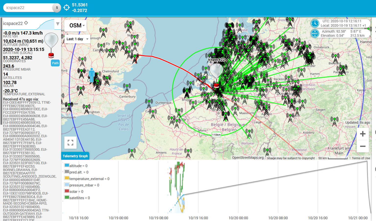
Jakub, in my high alititude flights from the United Kingdom, we have no issues getting our data picked up with SF8 and SF7. With direct line of sight, the spreading factor does not make a difference at all(from experience). Over the Netherlands, we have had nearly 400 gateways pick up our packet. See picture below. We have had good coverage over Belarus, Romania and Slovakia. At least 2 gateways pick up transmissions there.
You are better off transmitting more regularly at high data rates, while sticking to the 30s TTN airtime limit. Even if some packets are lost, you will have some that get through.