@aschroeder, Here are the instructions to do the mods and a photo.
Regarding the VDD_TCXO modification, in my opinion the best method is Option 2 that involves using a laser if you have access to one. With Option 1, there isn’t much space between the via and the Murata module to solder a wire to the trace after you drill the via.
Hi @LoRaTracker LOL! Off the top of my mind I do not think the star pointer will work well. I had access to an Oxford laser with a 20um spot size. They are used for laser micro machining, micro drilling, etc.
Thank you for the detailed information - great job. Unfortunately i think we have to wait for the next version from Arduino. Tinkering with an oxford laser is beyond our possibilities .
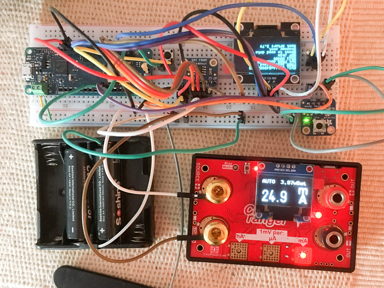
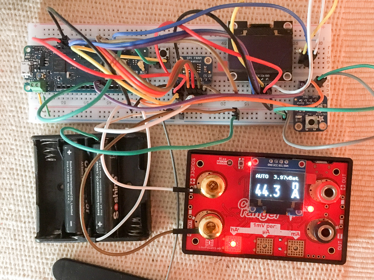
Pictures are misleading, I was out of battery holder so I add to hack a bit for testing
I actually use a single 700mA LiFePo4 – one of the 2 batteries in the picture is a ‘dummy cell’ used as placeholder (which can be used when you want to replace 2 ‘dry’ cells by a LiFe)
This is BTW another stupid annoyance of this device: it has an 1/3 voltage divider, so the maximum you can measure is 3v using the 1v reference. So by the time your LiFe reaches 3v, it is almost empty…
Hello Amedee
Sorry if the question is silly but how do you achieve such low current with the TPL5110? I looked at the specs and it says 20uA in Sleep mode. Am I missing something?
It sounds like the TPL5110 approach is an easy fix for nodes which are not low-power by design and only need to wake up at regular intervals. I have two questions if you may:
1/ from an energy efficiency point of view does it always make more sense (when possible) to completely switch off the device like above or can the overhead of a cold start be worse than a deep-sleep in some cases? Maybe this question very much depends on what’s in the Setup() function.
2/ in one of my applications I wish to wake the node through an external interrupt. I see that on the Adafruit TPL5110 board there is a button to manually wake the device. In your opinion could this be hacked and used as an external trigger?
Re. 1: it really depends how long you need to setup()… If you want to drive e.g. particle sensors which typically needs to warm up, the problem won’t be the sleep time but the overall power usage when awake. The few mA in sleep won’t weight a lot against the awake power. Also do you want to be awake once a day or every minute? that will make a big difference as well.
I typically use a very basic spreadsheet where I enter my awake/sleep power usage and duty cycle to get an idea on the theoretical lifetime…
But most sensors don’t require a long setup time.
Re. 2: absolutely it is not a hack it is a feature of the TPL5110, when you pull M_DRV to VDD it will wake-up your device.
I think I already posted it, but I don’t see it immediately, I have published a proof of concept implementation which can help you to start. I have nodes running now for months on a 700mAh LiFePO4 battery.
Now, in my opinion this is only worth if you already have MKR nodes. If you don’t already have these consider something else which is designed with low-power in mind.
I have been playing with various boards such as the AirBoard+mDot, the MKR WAN 1300 (where is rev 2.0…?) and the Adafruit Feather 32u4 lately but most of them don’t achieve low enough current in sleep mode to enable non-rechargeable-battery-powered nodes with long life-time applications.
I just discovered your blog as well as the MiniLora project which I might look at closer. Lots of really interesting reading ahead :))
One thing I am also interested in is how to handle sensors which require too much current to be powered through a regular digital IO pin. In such case it seems a mosfet is the way to go to switch them ON/OFF.
All this to say you might see me around every now and then with questions… and hopefully answers to newbees when I am savvy on the topic
@sebbad, I just have the same issue, and modem.sleep() won’t work because it’s not implemented in the AT firmware of Murata module, even if it’s on the MKR1300 library. That’s why it always return false and that’s a shame
Arduino just introduced the MKR13100 which appears to have fixed the sleep current. The power consumption is now as low as 104uA, says the LinkedIn message. According to Gianluca Varisco, Chief Information Security Officer at Arduino, the stack is the same as the MKR WAN 1300 so it supports both US915 and the legacy US915_HYBRID. Users of The Things Network in the USA still cannot use this, unless there is a fix to set the channel frequencies.
Yes, this is much better – you would need roughly a 950mAh battery to keep the node in stand-by for a year.
It is not ultra low power, but it is definitely much better than the previous version and probably good enough for most of us…
The new board is the MKR WAN 1310. The board also has the ability to disconnect the on board power supply and reduce power consumption to less than 20uA.
Yes, the power supply issues with the murata module have been fixed.
The majority if the static power consumption now is due to the linear regulator. There is a jumper now on the board to disconnect the power supply. So, if you use an external power supply, you can get down to less than 20 uA while sleeping.
[Slight tangent sorry - lot’s of good info here so hoping someone can assist!]
I have a custom board with the CMWX1ZZABZ-078 module. I have flashed the module with the MKRWAN1300 code - I want to use the AT SLAVE commands to control the module.
The image is built fresh from the github master repository. I flash it with a ST-LINK-V2 successfully. I can communicate with the module via UART and it responds as expected.
The module appears to be drawing ~3mA at rest which is a lot more than I was expecting. This is with nothing connected - no UART, TCXO unpowered (it routes to a solder jumper to facilitate testing), nothing but 3.3V in to VDD_USB (4), VDD_MCU (5), VDD_RF (6), and VREF+ (32). BOOT0 (43) is pulled to GND via 10K. All the GND pads are grounded, there are no other connections for this test.
Do I need to connect to it via UART and do any initialization to facilitate proper low power mode? Or should this work “as-is”…? Appreciate anyh insight either way
Setting aside the power concern for a moment, does it work? If not that might indicate the code is stuck in some sort of loop and not entering a low power mode.
You might want to try some other code to put the MCU and radio in a low power state.
 .
.

 and hopefully answers to newbees when I am savvy on the topic