any news about that module?
what news are you looking for?
What it now needs is to be made the same size as the Pi Zero, add in space for sensors and you have a small but powerful sensor node.
– Does that happen?
– Could it be ordered?
oh, right. nothing has happened yet due to other things getting in the way. I still need to revisit this at some point in the next couple of weeks.
thanks for reminding me.
Andrew
it would be nice having the following features: 
RGB LED, push button, prototyping area, SMA and u.fl antenna connector
I have problems with WiringPi. I can compile everything. When I start the program, I get this error:
wiringPiSetup*: You must only call this once per program run. This is a fatal error. Please fix your code.
The Data from my Raspberry:
Type: Pi 3, Revision: 02
System: Linux raspberrypi 4.4.13-v7+
Gpio Version: 2.32
gcc version 4.9.2
I’ve got this little board with RFM95 working fine on 2 RPI
I’m using it with tweaked version of LMIC (branch rpi)
Lot of examples here (more to come)
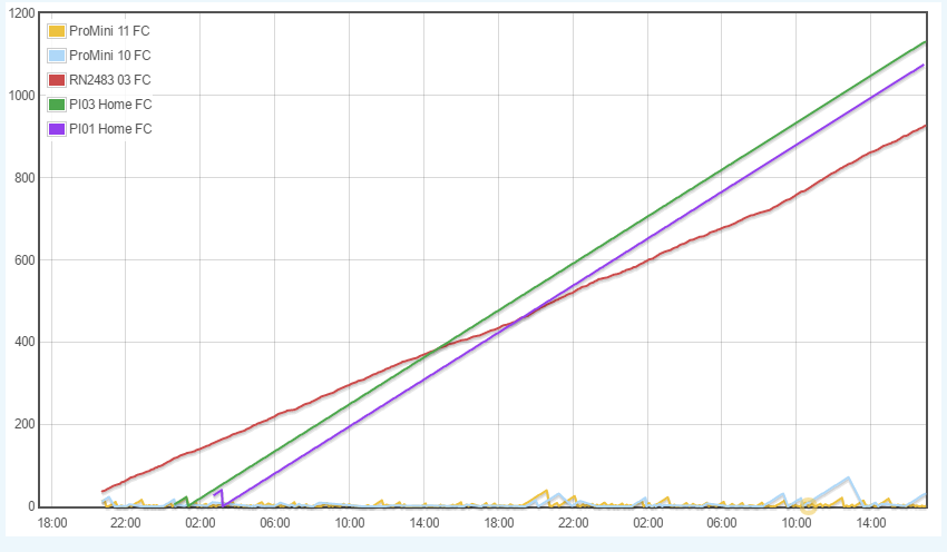
I’m currently monitoring Frame Count (with TTN -> Emoncms) of several devices to see if some have unintended reset
1 Like
For a ready to work RFM22+RFM95(Lora capable) raspberry pi shieldyou have the following product “chistera pi”:
Check the github for python/C code+Makefile from the product description:
github snootlab repo
So, it’s been a while, but maybe @ernestopace can also help me out here.
I’ve tried using your lmic_pi port to set up a node. But as soon as I’ve compiled thethigsnetwork-send-v1 and try to start it, wiringPi throws this error;
wiringPiSetup*: You must only call this once per program run. This is a fatal error. Please fix your code.
Since other people in this thread got this running, I assume it’s my mistake.
Maybe you (or anybody else here) has an idea what I’m doing wrong?
RPi Model B+ V1.2 & Adafruit RFM95W
@mkuemmel
I wrote a dedicated branch of LMIC working fine on RPI with LoRasPI boards, but should work with any RFM95 with same wiring
the source code of LMIC is there (note that git branch is rpi, not master)
@Charles
I just tried your LMIC.
So, there’s this problem;
~/LoRa/arduino-lmic/examples/raspi/ttn-otaa $ sudo ./ttn-otaa
ttn-otaa Starting
RFM95 device configuration
CS=GPIO8 RST=GPIO5 LED=GPIO4 DIO0=Unused DIO1=Unused DIO2=Unused
DevEUI : snip
AppEUI : snip
AppKey : snip
FAILURE
…/…/…/src/lmic/radio.c:692
Having a look into the mentioned file, this failure points towards the last line here;
// some sanity checks, e.g., read version number
u1_t v = readReg(RegVersion);
#ifdef CFG_sx1276_radio
ASSERT(v == 0x12 );
Edit:
Maybe I failed the wiring?
To be honest, I don’t fully understand your schematic.
I’d assume it’s
RST → GPIO 22
NSS → GPIO 24
G0 → GPIO 25
MOSI → GPIO 26
MISO → GPIO 28
SCLK → GPIO 30
?
@mkuemmel
This error means that it can not find the RFM95 module on SPI bus, what’s your physical wiring from PI to RFM module ?
would you post the result of spi_scan to see, here is mine
root@pi03(rw):~/arduino-lmic/examples/raspi/spi_scan# ./spi_scan
Checking register(0x42) with CS=GPIO06 => Nothing!
Checking register(0x10) with CS=GPIO06 => Nothing!
Checking register(0x42) with CS=GPIO08 => SX1276 RF95/96 (V=0x12)
Checking register(0x10) with CS=GPIO08 => Nothing!
Checking register(0x42) with CS=GPIO07 => Nothing!
Checking register(0x10) with CS=GPIO07 => Nothing!
Checking register(0x42) with CS=GPIO26 => Nothing!
Checking register(0x10) with CS=GPIO26 => SX1231 RFM69 (V=0x24)
root@pi03(rw):~/arduino-lmic/examples/raspi/spi_scan#
and then
root@pi03(rw):~/arduino-lmic/examples/raspi/spi_scan# cd ../ttn-otaa
root@pi03(rw):~/arduino-lmic/examples/raspi/ttn-otaa# ./ttn-otaa &
ttn-otaa Starting
RFM95 device configuration
CS=GPIO8 RST=GPIO5 LED=GPIO4 DIO0=Unused DIO1=Unused DIO2=Unused
DevEUI : ****
AppEUI : ****
AppKey : ****
16:47:53: Packet queued
16:47:53: EV_JOINING
16:48:02: EV_JOINED
16:48:07: EV_TXCOMPLETE (includes waiting for RX windows)
@Charles
I’m currently not able to ssh into it, since it’s at my workplace and turned off.
But I know spi_scan outputs “Nothing!” for all of them.
Physical wiring - I tried to copy what you might / should have with your LoRasPI.
5V & Ground from Pins 2 & 6
RST -> Pin 22
NSS -> Pin 24
G0 -> Pin 25
MOSI -> Pin 26
MISO -> Pin 28
SCLK -> Pin 30
Not sure (at the moment) about the corresponding GPIO-Numbers.
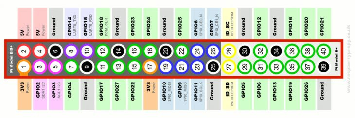
Ouppppppps 5V is not good, chip are 3.6V maximum so you need to connect to 3V3, the correct LORASPI wiring is has follow:
3V3 => P1 connector PIN 1 or 17
GND => P1 connector PIN 6 or 20
RST => P1 connector PIN 15 (GPIO22) you can leave unconnected
DIO0 => P1 connector PIN 22 (GPIO25) you can leave unconnected if using my LMIC version
MOSI => P1 connector PIN 19 (GPIO10)
MISO => P1 connector PIN 21 (GPIO9)
SCK => P1 connector PIN 23 (GPIO11)
SEL => P1 connector PIN 24 (GPIO8)
@Charles
Thank you very much, I’ll try this tomorrow morning.
I chose 5V because the manufacturer (Adafruit) said so? At least for their Arduino example, I doubt it would be different on an RPi here.
The ADAFRUIT board has input buffers and a voltage regulator, so 5V will be OK.
The error message about wiringPiSetup iscaused by a library change. The new version of the library dislikes multiple setup calls.
So, these have to be removed. I removed one call of wiringPiSetup() in thethingsnetwork-send-v1.cpp and one in hal_io_init() in hal.c.
This got rid of thewiringPiSetup error; unfortunately I didn’t get the code to work anymore.
Still testing.
@Charles
Okay, I changed the wiring to what you said.
But I still get:
$ sudo ./spi_scan
Checking register(0x42) with CS=GPIO06 => Nothing!
Checking register(0x10) with CS=GPIO06 => Nothing!
Checking register(0x42) with CS=GPIO07 => Nothing!
Checking register(0x10) with CS=GPIO07 => Nothing!
Checking register(0x42) with CS=GPIO08 => Nothing!
Checking register(0x10) with CS=GPIO08 => Nothing!
Checking register(0x42) with CS=GPIO26 => Nothing!
Checking register(0x10) with CS=GPIO26 => Nothing!
To exclude the obvious, SPI is of course enabled via raspi-config.
Edit:
Uhm… Well.
After I simply removed the RST wiring, I get:
$ sudo ./spi_scan
Checking register(0x42) with CS=GPIO06 => Nothing!
Checking register(0x10) with CS=GPIO06 => Nothing!
Checking register(0x42) with CS=GPIO07 => Nothing!
Checking register(0x10) with CS=GPIO07 => Nothing!
Checking register(0x42) with CS=GPIO08 => SX1276 RF95/96 (V=0x12)
Checking register(0x10) with CS=GPIO08 => Nothing!
Checking register(0x42) with CS=GPIO26 => Nothing!
Checking register(0x10) with CS=GPIO26 => Nothing!
So, I might get it working now.
2nd Edit;
Just tried ttn-otaa.
My device is recognized and actived.
Thank you so much!
Great it works 
I think reset line was not the issue, on old spi_scan version sometimes it was needed to execute twice
@Charles Beginner question: Why does only the first call (after a reboot) of ./spi_scan yield a result? Like this:
pi@raspberrypi:~/arduino-lmic/examples/raspi/spi_scan $ sudo ./spi_scan
Checking register(0x42) with CS=GPIO06 => SX1276 RF95/96 (V=0x12)
Checking register(0x10) with CS=GPIO06 => Unknown (V=0x2D)
Checking register(0x42) with CS=GPIO07 => Unknown (V=0x03)
Checking register(0x10) with CS=GPIO07 => Unknown (V=0x04)
Checking register(0x42) with CS=GPIO08 => Nothing!
Checking register(0x10) with CS=GPIO08 => Unknown (V=0x05)
Checking register(0x42) with CS=GPIO26 => Unknown (V=0x32)
Checking register(0x10) with CS=GPIO26 => Unknown (V=0x14)
pi@raspberrypi:~/arduino-lmic/examples/raspi/spi_scan $ sudo ./spi_scan
Checking register(0x42) with CS=GPIO06 => Nothing!
Checking register(0x10) with CS=GPIO06 => Nothing!
Checking register(0x42) with CS=GPIO07 => Nothing!
Checking register(0x10) with CS=GPIO07 => Unknown (V=0xE0)
Checking register(0x42) with CS=GPIO08 => Unknown (V=0x0C)
Checking register(0x10) with CS=GPIO08 => Unknown (V=0x07)
Checking register(0x42) with CS=GPIO26 => Unknown (V=0x5C)
Checking register(0x10) with CS=GPIO26 => Nothing!
I am doing this on a Raspberry 3 with the Dragino Lora HAT.
@dermatthias
because CE0/CE1 GPIO pins could be in a wrong state (not Output HIGH) that may interferes with chip select pins of RFM95, they are set to Output High at the end of the code
It’s fixed in next version 