The data rate of ADR modification can be found by observing the change of “datr” item in the JSON string of the uplink message.
However, how to check the change of transmission power of the device ?
The data rate of ADR modification can be found by observing the change of “datr” item in the JSON string of the uplink message.
However, how to check the change of transmission power of the device ?
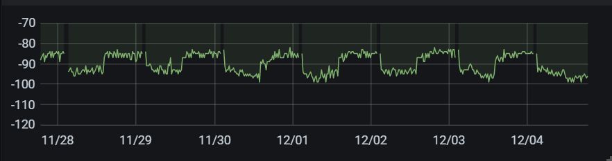
One method to see the variation in Tx power is to record RSSI into a database and display.
The particular node is about 500 meters from the gateway
I got it.
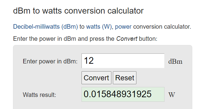
I found that the unit ‘dbm’ of RSSI can be converted to ‘w’, So rssi is the power itself.
RSSI is an indicator for the power-level at the input of the receiver. If you want to know the power-output of a transmitter you have to measure it there using a coupler and a spectrum analyser with appropriate attenuation. You can not exactly calculate the output power of a transmitter from the RSSI value of a receiver.
The RSSI values indicated by most of the gateways are more estimations.
It is true that, although RSSI can be converted into real power by mathematical calculation, as you mentioned, if this is only an estimate, there is no point in accurate calculation.
Always remember dB is a RATIO. It is the 10 x Log (Variable 1 / Variable 2)
So with power its Power (in dB) = 10 x log (P1 / P2)
Now if P2 is taken to be 1 milliwatt then the equation is
Power (in dB) = 10 log (P1 / 1 milliwatt)
And to save having to explain this in full every time there is a shorthand to say the reference or denominator was 1 milliwatt is to quote the power as dBm.
For example 1 Watt = 30dBm
(1 watt = 1000 milliwatts, Power (dBm) = 10 log (1000 / 1) = 10 * 3 = 30)
The important thing to remember is dB is a RATIO and you ALWAYS need to know the Reference value when quoting absolute values.
Formally to check the actual power emission you’d need test equipment, such as an RF power meter, or a spectrum analyzer.
Pragmatically speaking, apart from certification tests, people assume the chip does what it is programmed to.
So if you know the firmware has commanded the radio to a power level (perhaps because the firmware printed a serial debug message to that fact), then you assume that’s the case.
Or you can get a USB logic analyzer and snoop the SPI bus.
Or you can exploit the fact that the power consumption of LoRa radio chips during the actual transmission is heavily correlated to the RF power setting for at least the upper half of the output power range. So if a different power setting gets commanded, you should see different peak power consumption on the supply rail during the actual packet transmission.
A completely different way to “measure” the node’s transmit power could be to look at the code in the node and see if you can read the values it used last.
If you can read the last value of SF and Tx Power you could then send this as a variable in two bytes in the next packet. That way you could experiment and see how the system works.
If its only an experiment then you could get the Node to send this data to a computer connected to its serial port.
what are the units of the RSSI and SNR in the code that measures?
RSSI is in dBm, dB relative to 1mW.
SNR is in dB, ratio of RSSI to noise level.
i am testing some antennas in the loranetwork and i measure the RSSI value and SNR value in the uplink… but the code does not give me any units for these two values… so i guess RSSI is in dbm and SNR is in db?