Just a Hint on those cheap BluePill , that i use a lot too.
Check that R10 is 1k5 , there have been series (including mine) that had either 10K or 4K7 as R10. This prevents USB from working correctly as it won’t be detected with certainty.
I changed R10 on 12 of my BP’s in 30 min , using a Metcal w. the desolder “pincet”
Have seen mentions a few times elsewhere of resistor value issues. Good to note it here too to remind me and other to check it out as I for one will no doubt forget at some point and waste time scratching my head.
I had to use this guide (needs a ST-link) , and use st-flash , due to the combined bootloader & bin being > 64K if made w. my arm-compiler
Edit: Seems like there is a “trick” on the bottom of the page to combine the bootloader + blackmagic program , then you should be able to program it via “Serial” , and doesn’t need a st-link.
If you have a smaller image , and do the dfu-util to load the blackmagic code via the bootloader. Then the dfu-util 0.5 , that was in my Linux mint 17.3 repos , wasn’t new enough.
Anyone knows how to change the region for this board? The user manual gave very little information.
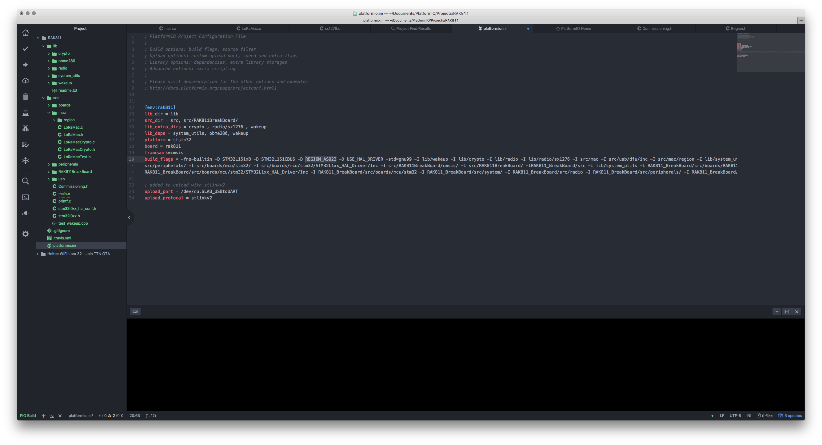
I am using Platform IO on a Mac - based on the information provided in this thread and successfully compile, flash and test the trackboard on EU868.
To answer my own questions - if anyone follow above instructions to setup your IDE based on PlatformIO, changing the region frequency is as simple as changing the build flag in you platformio.ini file in the project under PlatformIO.
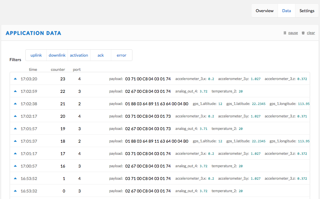
Now my RAK811 Trackerboard is talking to my RAK831 gateway with the changed frequency.
Hi guys,
You won’t be able to access low power on this board since GPS power switch has a wiring issue in schematics: a missing pull-up resistor makes GPS always on (this issue seems to be corrected on the other tracker board Rak815). A power led is also hard wired and won’t allow you to reach µA consumption anyway. and I’m not sure voltage regulators reaches low power mode (if they have one…). Thus this board cannot properly benefits from LoRa advantages.
Also, current source code doesnt allow you to reach low power mode: it checks for power supply type and is coded to always be “USB_POWER” (in timer.c TImerLowPowerHandler() ). just remove this condition or define “BATTERY_POWER” in GetBoardPowerSource(). Once you have done that, low power will work but LoRa connectivity won’t, because the board is put in deep sleep straight after starting joining process. What I did is replacing DeviceState = DEVICE_STATE_SLEEP after printf(“OTAA Join Start… \r\n”) by another state I added in enum eDeviceState: DEVICE_STATE_WAITCONFIRM. Sleep mode works properly, MCU consumes almost nothing but since others components like GPS are always ON despite of that, the board will still consume more than 20 mA in best cases.
@rchaudet Is it possible to manually modify the hardware to get rid of those low power issues ?
For example, unsolder the LED …
Maybe someone may need it, I ported the current version of the stack. It’s not finalized the GPS and MEM sensor are not working yet. See here: https://github.com/jobroe/loramac-node-rak811
There are two bits of software. One (which only seems available as binaries in “Firmware upgrade” in “RAK811-AT-Command”) reads from the keyboard and forwards your keystrokes to the RAK811, and forwards received characters from the RAK811 back to your screen. That code is more or less useless for tracking because it doesn’t read the GPS. It does, however, let you play with the RAK811.
The other (RAK811_BreakBoard) reads devices and (as you’ve seen) prints the status to the screen. It also tries to send what it reads up to Cayenne. Unfortunately, that code as programmed into your RAK811 Tracker is more or less useless because it doesn’t have your application’s id or key hard-coded into it.
In order to read the GPS and upload data to TTN, you need to recompile.
The code that handles the AT commands is only talking to the RAK811. In order to read the GPS, you need software running on the tracker’s microprocessor. That means flashing a custom binary, because the authentication details are hard-coded into the program.
Having read all the posts on this thread, I recommend that you go read the post I’m replying to. It has the best instructions on how to recompile the code on Windows. Mac users are using platformio. I just successfully used platformio on Ubuntu.
@rchaudet thanks for the information.
Related to :
GPS :
a. Can I use Power Saving Mode (PSM) triggered by command via GPS serial port to reduce power consumption? Maybe you haven’t done this, but please share if you have some insight.
b. On 811 board, I saw the GPS power is controlled by TPS27082 chip, and I can control to power off the GPS using PA15. I already test it using manual coding to turn On/Off the PA15 and checking the Power Consuption reduction. My application only required GPS position during Power Start, it’s not for mobility, so I think I can use this solution. Any comment maybe?
Power LED - I’m planning to just desolder this.
Other LED - I’m modifying the code to disable all status LED.
I will try your input for the DEVICE_STATE code modification. Thanks