HDOP: Almost, but this gives you a range of -12.9 - 12.8. Rather go with unsigned ints to get a range of 0 - 25.6 because hdop will always be positive.
Altitude: Why do you need centimetre accuracy, while the altitude accuracy you get from the GPS is in the order of 10’s of metres. Better to stick to metre resolution to save space.
Lat: You multiply by 10000, so you end up with a value in the range -900’000 - 900’000. You then store it in a 32bit int, which has a range of -2’147’483’647 - 2’147’483’648. You are therefore wasting (4’294’967’296 - 900’000 - 900’000 / 4’294’967’296 = 99.958%!
Rather use the format as suggested by @RussNelson, which can be found on github. This format was designed to not waste a single bit, therefore maximising the resolution and minimising the LoRa time on air.
I was wondering about the reason of choice one or the other format, (@RussNelson suggested to use yours) , thank you for the explain, it saves me a couple of hours.
I will use your format as soon as I get some free time
My purpose was just to give OlofAst another way to test.
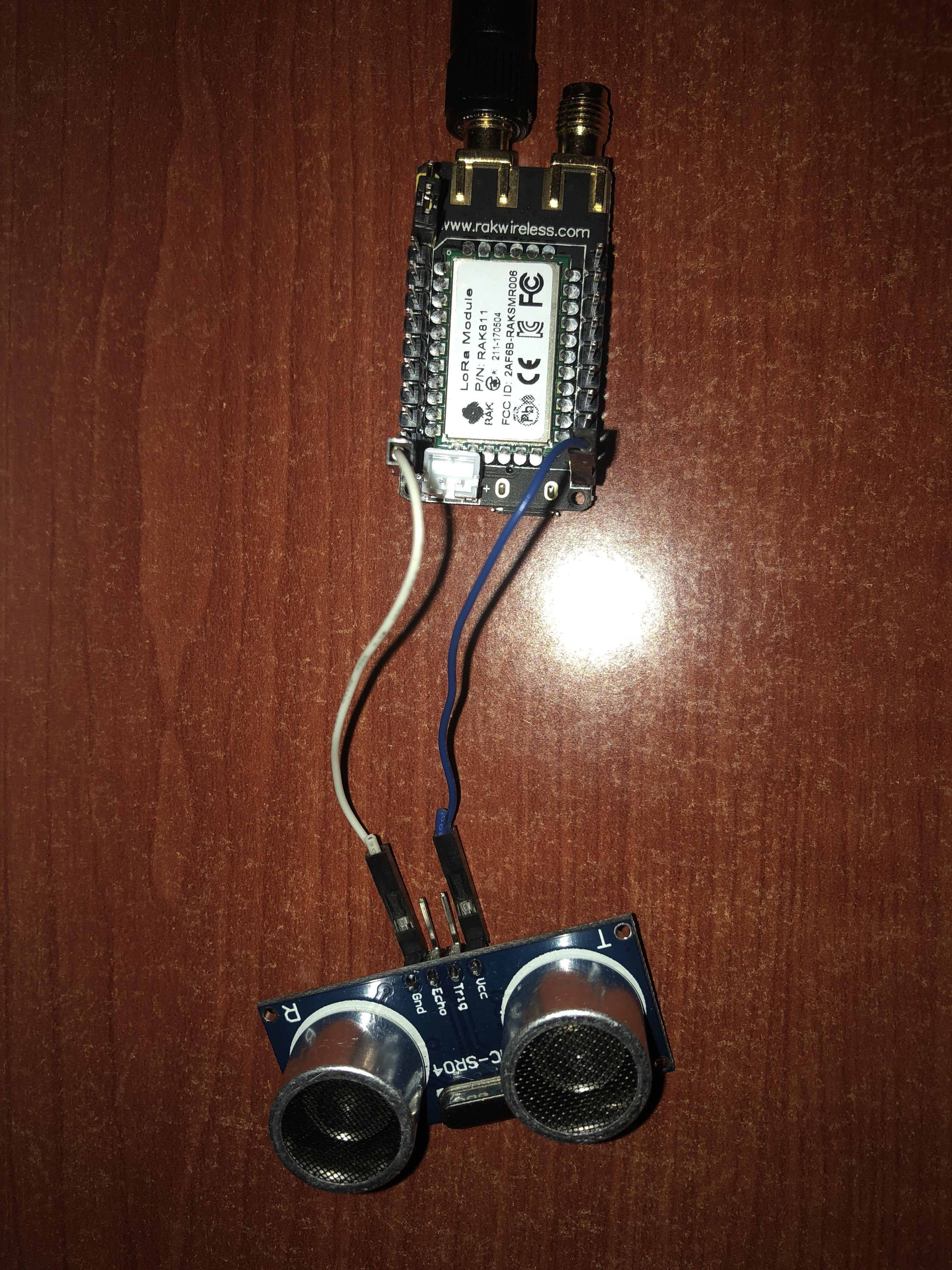
I’m trying to connect a ultrasonic sensor, I think I got vcc and ground, but just need 2 pins for trig and echo.
will the following pins work?
pinMode(PA1,OUTPUT);  // Physical pin PA1 on the board ?
pinMode(PA15,INPUT); / Physical pin PA15 on the board ?
digitalWrite(PA1,LOW); // Pin PA1 |   LOW is off / HIGH is on ?
digitalWrite(PA15,LOW); // Pin PA51
Has anyone tried RAK811 on mbed? https://os.mbed.com/
In MBED release 5.8.2 RAK811 support was added.
But maybe that is for a separate thread, will add one when I have time to look at this.
Anybody tried using the board without an external active GPS antenna? I did, and got no GPS fix at all.
My goal for today is to design a 3D printed case for the tracker, holding an 18650 battery and the tracker together. I dropped my tracker and bent the antenna’s SMA connector. Gotta protect the poor thing if I’m going out and about with it!
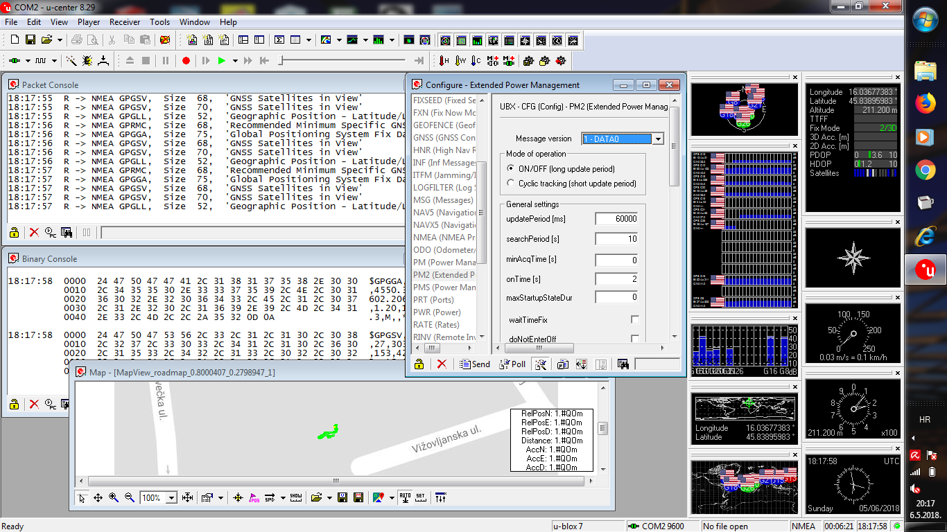
I have created code to bridge GPS serial and USB serial.
Idea is to set GPS to low power mode to send data only every few minutes not every sec.
GPS > USB is working nicely
I still do not know how GPS config message ends so I send byte by byte.
I do not see any change when I send config to GPS
Rak831? The lorawan gateway module? Why would you want to set the gps to low power for a gateway?
Or did you make a mistake in the numbers and are you referring to the rak811 (the subject of this thread)?
Progress. I have a 3D printed part that holds the battery and board together reasonably securely.
I have figured out how to talk to the software over the serial port.
My thought is to use one of the GPIO pins to put it into serializing mode.
That would let you enter the id and key of your application.
It will be stored in the EEPROM, along with other things like the delay between transmissions, and whether you wanted to upload the accelerometer data and/or battery data.
That, plus an integration with ttnmapper would let you do mapping without having to compile any code.
I could make binaries for any of the regions. That could probably also be turned into a run-time selection, but it would also make the code larger. I haven’t checked to see how close we are to filling up the code space.
I dont use GPS module (not soldered).
I removed power LED, software disabled LED1 & LED2. Now current consumption of board is:
Hold the RESET button - 39.5 mA;
Wait mode - 6.5 mA;
Transmit of packet - 68.8 mA;
Two short strange consumption after transmit - 22.2 mA.
Now drop of voltage is 70 mV per one day (18650). I would very much like to get values in microamperes in sleep mode.
I did as you wrote, but I can not put the device into sleep mode.
Are you able to share your code? Or working example, please.