RAK811 lora module is a different product to the RAK811 tracker/sensor nodes - which have you got?
I have a small batch of both Sensor and Tracker boards.
When I connect with Putty I see debug info coming in on serial connectionsand device functions ok, reporting voltage, temp, movement detection etc. but no way to interact with 1st sensor bd I’ve tried. Reset triggers info saying ABP and I can see pre configured NwksKey,DevAddr, Dev_EUI etc so was looking to replicate the “connect to things network v1.0” doc…and basically reset and move to OTAA…
Any hints?!
Yes, ok so the tracker and sensor boards - I have a 3 of them, they are complete lora devices that include the RAK811 module, before delivery RAK preload them with test code for testing and that is what you are seeing - coding/compiling will be needed to rebuild the device for your own TTN applications etc (I’m assuming you’ve done a little on TTN setup of OTAA/ABP devices etc, if not you will need to read the TTN support pages  ).
).
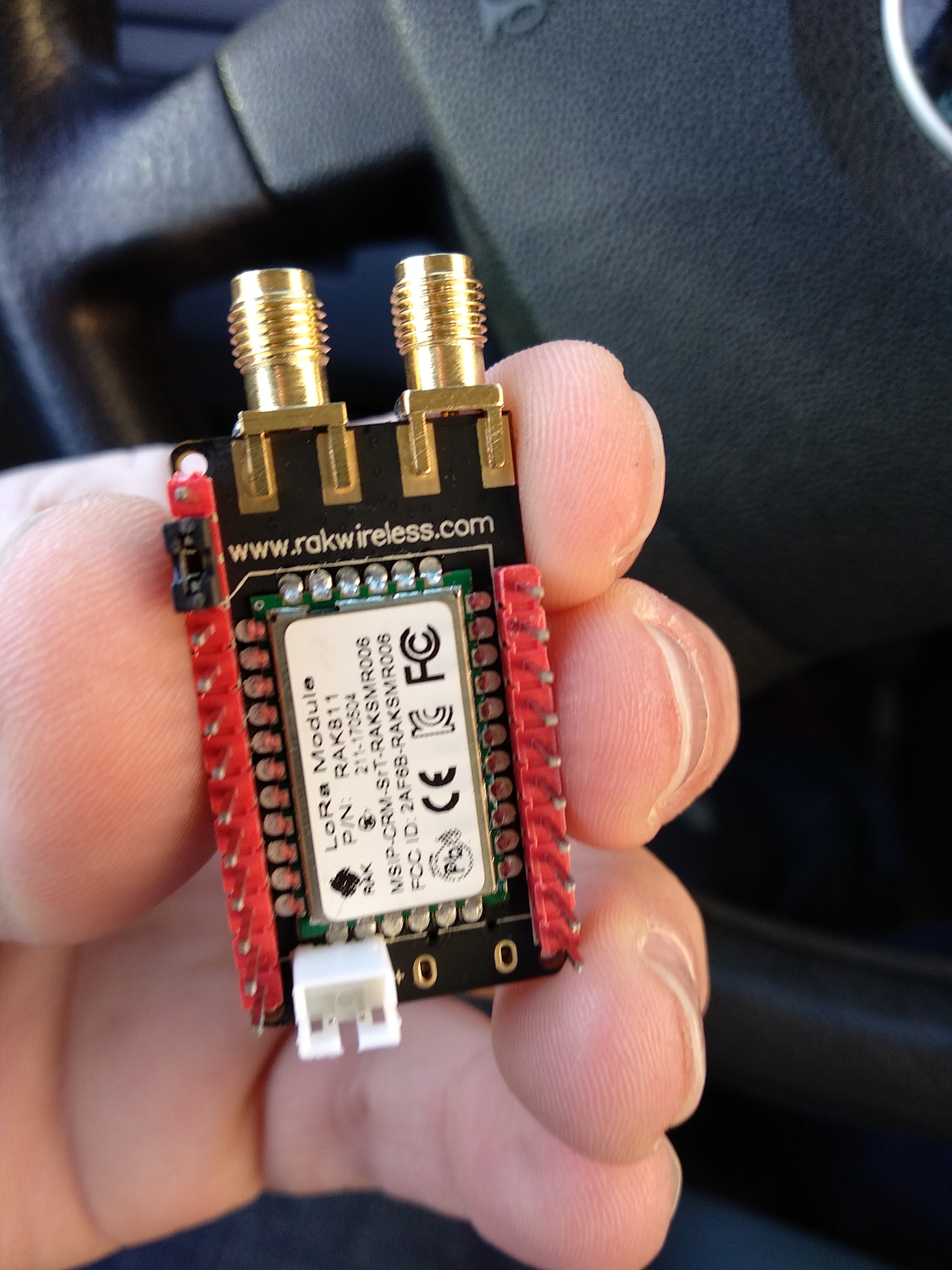
Important to remember that the RAK811 lora module park is a bespoke lora module (equals a STM32L151 MCU + SX1276), the tracker and sensor nodes are whole boards wrapped around one of the RAK811 modules.
The RAK811 module can be used in two modes, 1) as a dumb AT command peripheral that is then connected to another MCU that issues the AT commands, 2) as a fully functional remote device where the STM32L151 is the control MCU - this is where code compiling comes in - see this thread
The tracker and sensor boards are the ‘deeper end’ of lora devices setup, but lucky for us this thread does walk you through the source code, making custom changes, compiling and burning the firmware.
Thanks Jezd, figured the pre-config/test code was the case but had hoped to follow the method used in the “How To Connect LoRa RAK811 To The Things Network V1.0” app note from their web site (specifically Part 6 steps 6/7 using AT commands to set config/load keys etc.) without getting into sw builds & compilation (though that doc ref’d WisNode LoRa EVB with 811 I dumbly assumed same procedure for serial control over the microUSB)…ah well, have CoIDE downloaded so looks Like I have to get it installed and take the long way home!  that’s one for tommorrow …cheers!
Ok.
I know that I have have WisNodes, but from a hardware perspective they are not that different from the tracker boards. The code for both is very similar. (It is available on Github)
I had RAK provide me with a version of tracker firmware that would run on my WisNode hardware. This allows me to use these devices for tracking/network range testing.
The device sends Cayenne LPP style temperature (fabricated, as no temp sensor on WisNode) and GPS data.
The board sends the debug/status data out the USB port and it also accepts AT commands on the USB port. My understanding is that the firmware I have was derived from the Tracer board firmware (just reconfigured to suit my AU915 requirements and the WisNode hardware pin connections). I did not make any alterations to the firmware. RAK provided this to me to help with my testing.
You could try loading firmware, like I am using, as an initial test of your setup and network connectivity. Once you understand that, then you could revert back to your custom application code.
Just a thought.
Cheers
Peter.
Sorry, to clarify Peter,
Did you have to ask the RAK guys for this firmware directly? Or is it on the RAK website/wiki somewhere?
I have struggled to get my RAK811 sensor node working , I also have AU region implementation.
Hi Phil,
I asked RAK directly for the firmware (binary).
I didn’t have time to try and attempt to modify the software from the source code and my knowledge of doing so is very limited.
I would suggest you contact me via direct email and I can share the binary with you.
Cheers
Peter.
Thanks for heads up Peter, will try to take a look at that also over next day or two.
Did you mean to have a hyperlink here?
no I was talking about ‘this thread’ you are reading
1 Like
FYI. I have a Single channel gateway, but never got OTAA to work with this gateway.
Try ABP instead, it might work better.
https://www.thethingsnetwork.org/docs/devices/registration.html
Another tip is to disable frame counter checks so you dont have to reset the framecounter each time you restart your RAK device.
I will check the application data while debugging,
I drive some with the car very near to 3 different active gateways in my surrounding (becaus I have no own one).
Maybe I have really to wait until my ttn gateway arrives, but I am afraid this will be not early…
Hi @OlofAst,
Great work with https://github.com/Ebiroll/RAK811_BreakBoard and Thank you!
I am able to use to join TTN with OTAA without any problem.
Infact, Im able to flash the binary with STLink V2, just with pio run --target upload
And All from a mac.
I have one question. Does this acquire the GPS?. Im yet to look into the code. But wanted to check with you meanwhile.
PS: Im able to see GpsGetLatestGpsPositionDouble ret = 1 in the serial outout.
1 Like
This version has Makefile 
I have tested it and it maps …
I saw that it gets data from the GPS, but I have not verified that it looks ok on the map. Someone reported that it get stuck on SF12 after join.
I have added support for BME280 sensor over i2c and will put the chip into sleep mode as soon as I get some spare time.
There is also instructions on how to run the code in an emulator, startup code in platformio differs from the makfile version.
I just added missing -DUSE_HAL_DRIVER, but there should be no big difference.
3 Likes
Mapping is working…
3 Likes
Some step-by-step installation manual for beginners for rak811, please.
Keli5 and another software.
thank you very much
have you read this thread?
yes, I do not understand very well the explanation of the manual, there are many steps that are taken for granted and I do not have that knowledge.
For example keil and J-Link or
Remove startup_stm32l151xb.s from the project as this is in a Keil specific assembly file
Create a new solution using the project template for STM32L151CB. You won’t use this but its a quick way to get the right files
From that solution directory, copy the xml files for flash placement, memory map and registers. Also, copy all the assembly files (.s extension) and the RTT files (see the segger directory in my project)
Add the assembly files to your project
Reconfigure the project options to point the linker etc to the xml files mentioned above
Build and you should be good to go ------------- ???