I cannot see any output after I typed
at+version
and press send.
I cannot see any output after I typed
at+version
and press send.
It wont work, you dont have the AT ‘firmware’ burnt in, have a read further up this thread
Under the impression of the official documentation, I thought the RAK811 tracker board came in with the firmware burnt in out of the box?
It has tracking firmware burned in but not the AT command firmware. The tracking firmware won’t work though without changing the keys for TTN
Would be useful if rather than just the ‘as shipped’ test code - (can see packets arriving at gateway on TTN console so at least useful for checking capture and combined with Phone GPS am using to test range  ) - it came with option for tracker and/or AT command based on say a 2sec or 5sec button push at power up (on a GPIO pin or pair if not practical from existing (reset button). Tracker & Sensor bds promoted as easy for use with TNN but reality is need to get in and hack (reprogramme) - sorry about that @coeus - caught me out too! @rakwireless…over to you guys
Does it mean one has to perform a firmware flash from RAK Wireless’ github so the board can be configured by AT commands?
And I assume the latest firmware is listed here?
https://github.com/RAKWireless/RAK811-AT-Command/tree/master/Firmware%20upgrade
Yes, you can do that but then it effectively becomes a dumb module - the same as the Rak811 boards you may connect to the arduino for example. The AT command firmware is designed for the Rak811 module only and doesnt support any of the other sensors or GPS on the board
Many thanks for your reply. I think this is very confusing… flashing official firmware will lose some functions that was advertised officially?
I think whats confusing is Rak811 is used for the module and the name of the board.
This board is known as the Rak811 Tracker and its firmware is the Rak811 BreakBoard firmware. It replaces the firmware in a Rak811 module using the microcontroller directly with an SX1276 radio in the module. This is similar to say an Arduino running LMIC. By using the microcontroller in the Rak811 module, it saves power and allows the use of the external peripherals
The Rak811 module has its own firmware for standalone use which is the AT command firmware. This runs the LoraWAN stack only and allows an external microcontroller or PC to communicate with the module to send and receive data - the intelligence is all in the external host.
Flashing the Module firmware on the Tracker board sets the module up as a standalone module. As such you can use the AT commands and send / receive data but it expects the intelligence to be on an external processor. I’m not 100% familiar with the functionality but I suspect serial and I2C are not available through AT commands and as such the GPS and accelerometer won’t be usable. You can, however, test that the board works.
For normal use, this is really considered a development board that you need to define your own code for using the breakboard project on GitHub. THis is based on the LoraMAC code I’ve previously mentioned although its a much earlier version.
It would have been nice if Rak had provided some commands to change the keys for the board over serial using the breakboard firmware as it would then be immediately useable as a tracker.
You mentioned you maybe able to provide some “how to lab file” I have my board hooked up via the recommended CooCox setup and able to compile the file successfully and copy it via the Segger Jlink to the board. However I must be missing some values in the main.h as I can not make it work. The hardware looks good but support is very limited. Can you help? maybe you have a main.h file you can comment on the values which have to be changed. I’m new to this and it has been a real challenge.
I’ve got now everything worked, Also GPS is working (seen with printf in main.c).
After starting the debugger I see only activation at ttn console, but no further payload.
Does anyone has an idea why.
@rakwireless can I suggest a poss improvement/change to board design. Playing with a few 811 tracker and sensor boards it seems that as soon as either USB pwr or a battery connected the device kicks in with no way to shut down other than disconnect battery or remove usb power - indeed need to disconnect both. I am building into small housings with just usb and Ant connections exposed with (now difficult to access) rechargeable batteries embedded and its annoying that operation starts immediately and batt life obvious starts to run down.
From a quick scan of schematics it looks like the EN pin of the MIC5219 3.3v regulator is hard wired to VBatt. If I understand correctly then if that pin left open or brought low device shuts down down stream of the regulator with v. small quiescent current or poss charging current from USB if on charge. Is it poss to change design to bring that pin to a header that can then either be jumpered high (say on a 0.1inch pair) for those who want always on or brought out to a simple spst switch to take high for those who want a basic on/off function? That also allows for device core to be off but USB pwr then used to charge battery as and when needed. Please advise options/practicalities as may have to switch to alternate board type (alt vendor) or commission custom design if I cant resolve, thanks.
If any forumites have alternate solution please shout!
+1
I’m just starting with this board, and that would be critical for my applications. Would love to be able to make use of a pre-existing design, but otherwise will have to do my own. Once I’ve evaluated the RAK811 module I can determine if it is suitable to use in my own design - so at least the sample board is helpful for that.
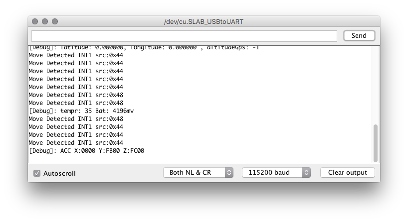
Anyone here know how to display the current voltage (or charged percentage) into Cayenne? There are blocks of code in board.c but I thought I should ask while I dive into the code.
I think there’s a debug message coming from the serial output with battery voltage so it’s definitely do-able I reckon.
How to Edit and Upload the code without a J-Link on Win10 and Atom
Download Atom.
Once Download, install and open Atom up.
Then go to settings > install, search for platformio
Install the following.
platformio-ide-terminal
platformio-ide
platformio-ide-debugger
Once done, download and install the comm drivers for the RAK811
http://docs.rakwireless.com/en/RAK811%20TrackerBoard/Tool/CP210x_Windows_Drivers.zip
Then download the git from OlofAst
open Atom, on the PlatformIO Home Tab, go to Platform
Search ST STM32, Install
Then click Reveal
It will open up a Explorer window, then open folder ststm32/boards
copy the file from OlofAst’s git, rak811.json to the ststm32/boards folder.
Then in Atom, click open folder.
Open the folder RAK811_BreakBoard from OlofAst’s git.
Then open the Terminal in Atom
To edit the DevEUI and etc… open the file src\Commissioning.h
Save, and close the tab.
Now to Compile.
In the Terminal window in Atom type: pio run
if you see SUCCESS, compiling went ok
Calculating size .pioenvs\rak811\firmware.elf
text       data     bss     dec     hex filename
53236      1628    5244   60108    eacc .pioenvs\rak811\firmware.elf
===[SUCCESS] Took 12.25 seconds
Now to Upload .bin file to the board
Change the jumper on the board.
Connect the usb, go to Device manager and check what is you comm port number for the board.
Then in the terminal window In Atom, run the following
stm32flash_src/stm32flash.exe -w .pioenvs/rak811/firmware.bin COM5
This will upload the .bin file, the result should be
stm32flash 0.5

http://stm32flash.sourceforge.net/

Using Parser : Raw BINARY
Interface serial_w32: 115200 8E1
Version      : 0x31
Option 1     : 0x00
Option 2     : 0x00
Device ID    : 0x0429 (STM32L1xxx6(8/B)A)
- RAM        : 32KiB  (4096b reserved by bootloader)
- Flash      : 128KiB (size first sector: 16x256)
- Option RAM : 32b
- System RAM : 4KiB
Write to memory
Data size: 54868 bytes
Erasing memory
Wrote address 0x0800d654 (100.00%) Done.
You should all be done. Unplug, change the jumper back to original position.
Power up the board and it should connect to the AP.
To monitor the board, download Uart Terminal, Connect to the Comm port of the board, at baud rate 115200
RAK811 BreakBoard soft version: 1.0.2
Selected LoraWAN 1.0.2 Region: EU868
OTAA:
Dev_EUI: XX XX XX XX XX XX XX XX
AppEui: XX XX XX XX XX XX XX XX
AppKey: XX XX XX XX XX XX XX XX XX XX XX XX XX XX XX XX
OTAA Join Start…
OTAA Join Success
I’ve done all this on windows and I get over 400 errors during compiling.
Such as
src\boards\mcu\stm32\STM32L0xx_HAL_Driver\Inc/stm32l0xx_hal_adc.h:550:32: error: ‘ADC_ISR_EOSEQ’ undeclared (first use in this function); did you mean ‘ADC_ISR_EOC’?
Am i missing something…?
thanks for this step by step breakdown @quintin5010, this is really useful for those of us who cannot manage to read the 177 posts in this thread!
Things are looking up.
Downloaded a fresh copy from GIT and first compile goes through without errors. Must have had some corruption somewhere.
Now to see if it will Upload and then get to playing.
Hi
Try to use the following repo.
Had a lot of issue with the original one from Rak, this was the only one that works.
Now we’re cooking on gas.
Popped in my TTN App Device details and hooked it up to TTN Mapper.
Working like a charm.
Now to get it mapping independently of my smart phone ready for a future mapping wardrive.