Since you are Descartes, I guess you are referring to George Berkeley ![]()
Hopefully the missing power and ground connections in your schematic are actually there. You can probably get away with only using one ground connection to the RFM since it is a PCB, but you absolutely must connect all of the power and ground pins on the ATmega, in particular leaving out the analog one causes odd behavior in non-intuitive ways.
Also you are hopefully shutting down the ADC and its reference after use.
Be vary wary of signals asserted against pulling resistors.
Communication lines (serial etc) can either donate or steal current, a node may very well run off power stolen from a debug serial port or in circuit programmer up until it tries to transmit or receive at which point it will brown out. In other configurations such a connection may steal power.
Also never drive an I/O to a powered off component, it is generally out of spec and even if it does not cause damage it will be a power drain.
You may want to leave this thing running for hours on something that profiles what it actually uses. An INA219 hanging off another Arduino might work if you increase the sense resistor and bypass it with a capacitor - it may not accurately read the actual sleep current, but with some work on the current monitor Arduino sketch and running its output into a serial log program on a PC, you should be able to at least get a good idea of when it was awake and for how long, and to see the transmit and receive operations. I have mine rigged to start integrating any time power rises above the sleep baseline and then print out a total of microamp seconds when it goes back to sleep - I then merge the monitor output with the node debug output and I get logs to the effect of:
“RX1 at frequency…”
“no packet received” followed by an injected
“Current: that cost xxxxx microamp seconds”
Part of the goal there is to make sure software doesn’t get into a state where it is being far more active than it is supposed to. A watchdog can be useful, too - even if you have to wake up every now and then just to service it.
To measure the sleep current, rig the node to wake up do a transmit/receive cycle then go permanently back to sleep. You won’t get enough power through your meter on its most sensitive scale to run the node, so rig a clip lead across your meter leads and power up the node with that in series. After it’s done transmitting, remove the clip lead and see what you actually measure while sleeping.
No, I’m thinking René Descartes - I think therefore I am - or in engineer terms, I deliver therefore I contribute.
From my perspective, you have produced an interesting minimalist device so I am intrigued - so I’ll have a look and perhaps setup a test rig - watch out for a message.
But here’s the rub, this forum is for supporting LoRaWAN on TTN and at present LoRaWAN isn’t supported by RadioLib and you aren’t routing messages via TTN so this is off topic.
You mean the AVCC and AGND? No, it’s isn’t connected. Since is working without, i thought it isn’t necessary. I will connect them to VCC and GND
It’s done via the low power lib:
LowPower.powerDown(SLEEP_8S, ADC_OFF, BOD_OFF);
I like the idea with the INA219, it isn’t expensive and I will get continous data. I’m not sure if I understand what you mean by " increase the sense resistor and bypass it with a capacitor", but I think to check where the leak is, normal connection should be ok.
That’s really important. While I don’t have proof it happens, I could easily see high power consumption being one of the sorts of subtle and non-intuitive misoperation that occurs when part of the chip is unpowered - eg “I’m not using the ADC why do I need the analog supply?” (one does anyway… but then you are using the ADC).
I like the idea with the INA219, it isn’t expensive and I will get continous data. I’m not sure if I understand what you mean by " increase the sense resistor and bypass it with a capacitor", but I think to check where the leak is, normal connection should be ok.
The sense resistor usually shipped on experimenter boards is too small to measure tiny currents very well. Switching to a larger resistor will do that, but the circuit may operate poorly with a high impedance power supply, and the ADC may end up undersampled, so putting a capacitor across it helps smooth things out a bit. You’re not really measuring instantaneous power with an I2C sensor anyway, more “very short term average” for events that may take 10’s to 100’s of milliseconds. (Don’t try to print all the data, measure frequently, print an average over a longer timeframe, and ideally an integrated total for each individual excursion above sleep current such as a tranmission or receive window, or waking up to read some sensors without transmitting)
Indeed.
I did try the code being used, and noticed that pin 8 was being set high, but there is no mention of it here;
//pins for RFM98W
#define RESET 9
#define NSS 10
#define MOSI 11
#define MISO 12
#define SCK 13
#define DIO0 2
#define DIO1 3

SX1278 lora = new Module(NSS, DIO0, RESET, DIO1);
I noticed because most of my boards by default have an LED on pin 8.
So I tried an example from the RadioHead library, and that did the same, in fact configuring pins 6,7,8, as outputs and setting them high. Why would the library do that without apparently being asked to, it could cause all sorts of issues?
You would need to work out why this non-TTN library is doing that, but not in here …
Thank you @LoRaTracker for all the effort, i really appreciate it. Since I want to move to TTN anyway, any recommendation for an atmega ttn library?
By the way, this is my test device. In idle mode I can’t measure the Voltage, because my multimeter has mV only. 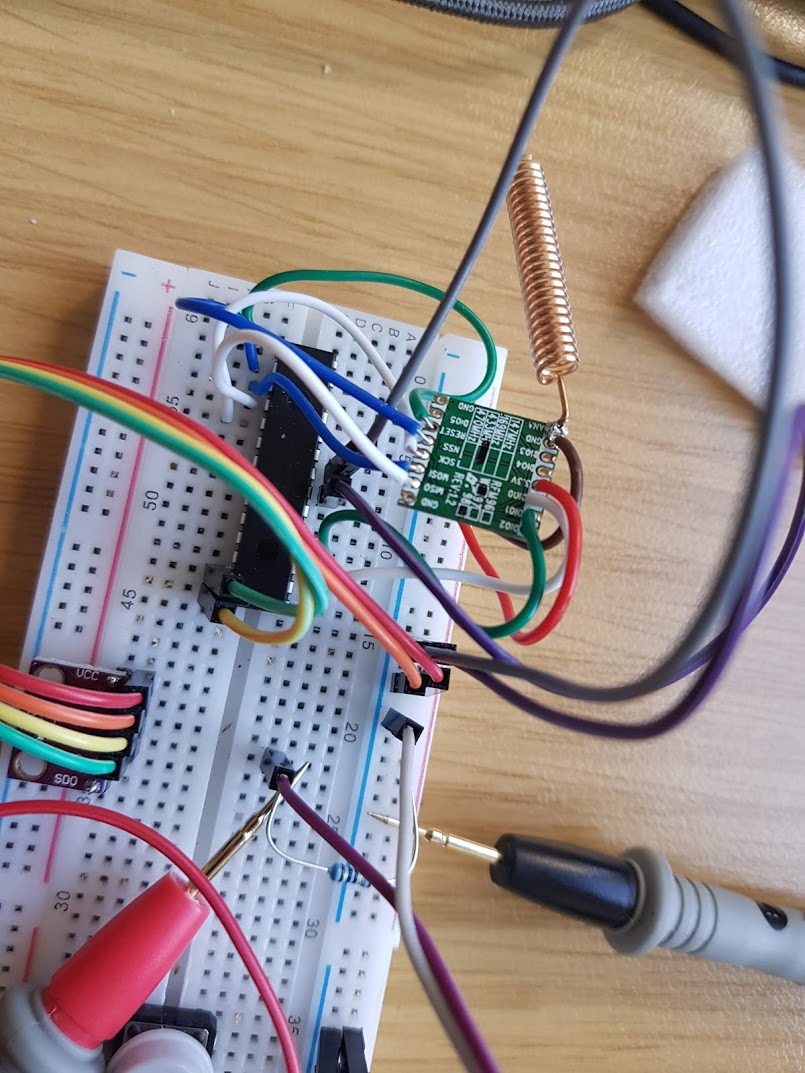
And I will connect the AGND and AVCC pins.
This works:
and there’s someone on here who can answer questions ![]()
1 Like
Thank you all for all the help. I really appreciate it. I will let you know about my results. Happy holiday everybody.
Summary:
- Connect AGND and AVCC
- Measure Current or Voltage over Resistance continuously and log it to file or similar
- switch to LMIC for TTN
There are low cost multimeters that will log to file via a PC application, the HP-90EPC for instance.
There are USB power meters that will give a running total of maHr, these can be handy, an example is the UM25C.
Alternativly use very low capacity LiPos, say 100mAhr or less, you dont need to wait so long.
1 Like
Hi. Recently I bought two SX1276 to work with 2 Arduino Mini and Pro to get started with my LoRaWAN nodes. Also, I received today my Heltex HTCC-AB1 which will be with a Raspberry Pi do work as a LoRaWAN 1 channel gateway. I suggest you use 3xAAA or AA. Could be better and easier to regulate from 4.5v and to handle with low power over time in your project.
I would try to reply to your circuit and test with an oscilloscope in a few weeks.
There is no such thing. Any LoRaWAN compliant gateway needs to receive multiple channels at multiple spreading factors. Please do not use one channel abominations for TTN as they disrupt the normal functioning of the network.
I don’t - it means you have to introduce more components which will have to be on all the time and won’t be able to power the circuit when they have drained the batteries below the regulators cut off, even for an LDO / super-LDO this will reduce runtime.
Whereas as properly configured 328P can rock on at 8MHz (aka a hacked Pro Mini, remove the Vreg & LEDs) down to 2.4V which is pretty much two very flat batteries.
At some point in the near future I’ll try @mcgreg’s circuit because if I set the fuses right and get a bit of a tail wind, at 4MHz you can drop to 1.8V.
As for the Heltec module, @kersing can sleep easy, the Cubecell range is either an Arduino LoRaWAN client or an AT over serial device - it will take more effort to hack it in to a single channel gateway which we all know is not LoRaWAN compliant and is disruptive to the network, than it would be to buy a PyGate or a TTIG or a board to sit on the top of the Pi and be a real gateway. Yes, technically possible to hack the hell out of a CubeCell to drive the ASR6501 SiP as a gateway but why?
2 Likes
Thanks, Jac.
Actually, 2.4V which is to say 1.2V per cell is a fair ways from “flat” for an Alkaline where the discharge curve of useful energy really runs all the way down to a volt. And that’s especially true at the kind of light currents being used. Fortunately both the SX127x and the SX126x can operate down to 1.8V in a carefully designed system.
Of course it’s also true that a linear regulator from a 3 cell voltage is going to be wasteful.
Many modern ultra low power radio systems are now using switching supplies, sometimes to run core parts at voltages lower still - eg, see the sx126x docs.
Hi.
If you want to measure and estimate battery life, this is good tool for you.
Thanks
Keep the maximum power it can provide in mind:
up to 150 mA
For those with deep pockets, check the Qoitech OTII. Excellent tool for professionals but probably too pricey for the avarage user.
Free software! But will need:
To be the hardware that does the actual measuring on the OP’s 328P
Guys, my motivation drops as quick as my battery energy 
First, I connected AGND to GND and AVCC to VCC as suggested. Somehow I can’t read the voltage via software anymore, I got always 5.2 Volt (sic!) via the “Read 1.1V reference against AVcc” and no, I did not touched the AREF pin. No expansion for the battery lifetime.
Second, I hooked up an INA219 to an Arduino Nano and connected it to my LoRa device. I’m measuring 10xsecond, create a second avg and print it to serial monitor.
I also changed the sleeptime to 60 seconds for the test.
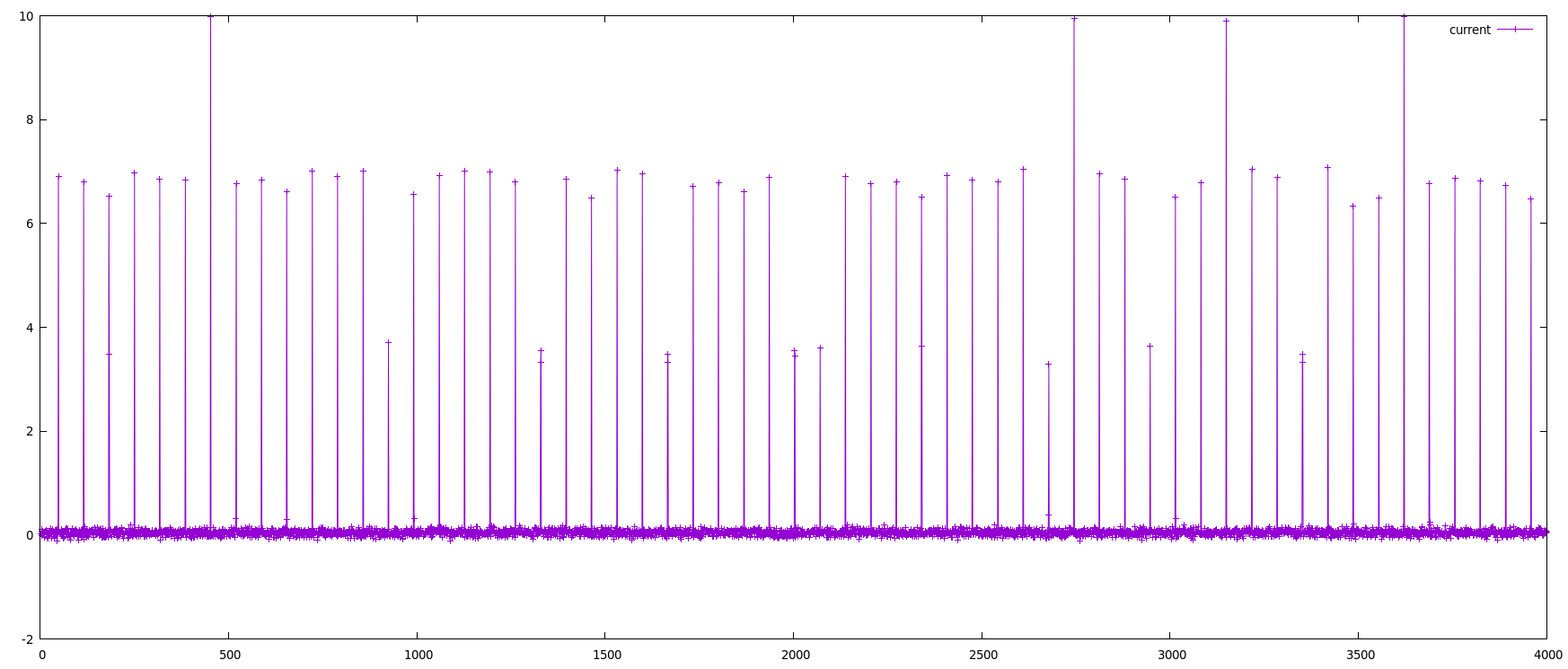
After 12 hours test, I see nothing odd: Consumption is around 0 mAh on idle, when sending data I have peaks which are around 7 mA per Second. So my power consumption is at total avg at 0.16 mAh, see attached an one hour example.
One thing I don’t get is the voltage. The load voltage (loadvoltage = busvoltage + (shuntvoltage / 1000) is always around 1.00 V. That can’t be true, can it?
The only conclusion I have is the power supply. Are ALL my batteries so bad? When they last 30 days with an avg @0.16mAh it means they should be 100mAh only. I did use brand new Eneloops (purchased in July 2020) and GP Super AA Alkaline.
During porting to the TTN library, I was also too stupid and had some issues (the device signature was slightly different) uploading it to one of my Atmegas, so I used the avrdude -F flag, since than, my device is dead. Well, it’s really a steep and stony path till now.
7mA is about right for the processor running with the LoRa device on and not in sleep mode. It is most definetly not the currnet consumption when transmitting, so you cannot use the 7mA to calculate battery life.
The packets are probably too short (time wise) for the current to be measured by most meters, so to see what it is increase the packet length by sending more data and setting the spreading factor to 12.