I did not take that picture seriously, most all of the connections you need are missing.
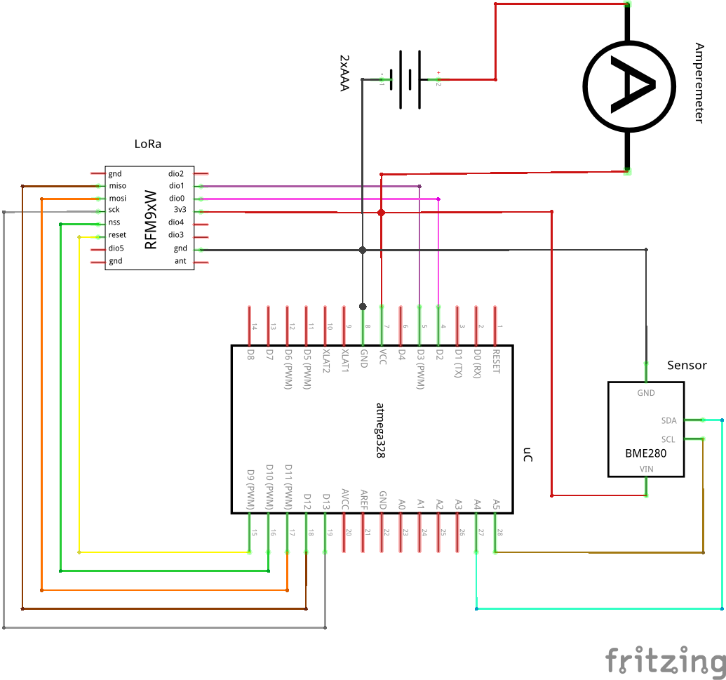
The full connection drawing is here (with the Amperemeter):
Take 10ohm resistor insted of ampermeter and measure voltage on it. Voltage/resitance=current. You will see the real power consumption. Then get back to us. Post picture of your hardware. So we see how it looks like in real
1 Like
Looking at a data sheet for the Procell AA (the industrial version of Duracell), they start at around 1.6V and quickly settle on a 25mA load to 1.45V and then slowly downhill from there:
So two new alkaline AA’s should start at 3.2V and drop to around 2.9V.
Your chart shows it starting at 2.4V.
So, how are you measuring the voltage? Different circuits will give different results and/or drain the batteries rather quickly.
I personally use Lithium batteries as they start out higher and have a much flatter drain and less self-discharge, but your measurement circuit could still drain those almost as fast.
As @slaven96 suggests, let’s see an actual picture of your device.
The Chart is showing the AAA Eneloop NiMh.
I will test it @slaven96 suggested. It might take some days, since I’m on vacation from friday.
Your previous current measurements, whilst worth checking as above, are in the right ball park.
BUT …
this could be the issue. We could have it fixed in the next hour if we know how you are doing it.
I’m measuring the voltage via software, so there is no different circut involved:
//see https://www.instructables.com/id/Secret-Arduino-Voltmeter/
` // Read 1.1V reference against AVcc
// set the reference to Vcc and the measurement to the internal 1.1V reference
if (ADMUX != (_BV(REFS0) | _BV(MUX3) | _BV(MUX2) | _BV(MUX1)))
{
ADMUX = _BV(REFS0) | _BV(MUX3) | _BV(MUX2) | _BV(MUX1);
// Bandgap reference start-up time: max 70us
// Wait for Vref to settle.
delayMicroseconds(350);
}
// Start conversion and wait for it to finish.
ADCSRA |= _BV(ADSC);
while (bit_is_set(ADCSRA,ADSC)) {};
// Result is now stored in ADC.
// Calculate Vcc (in V)
vcc = 1.1*1024.0 / ADC;`
OK, so we are clear no external voltage divider is involved.
I doubt the ADMUX is contributing to some mysterious drain as that would have been included in to your measurements above.
Next thing to check is that the device isn’t doing something when it’s not being watched (a bit meta, but if you are measuring, taking away the measuring device may cause an unexpected effect).
What software library are you using? Can you post your code?
Sure, here is the code.
#include "LowPower.h" //set the chip to really low power sleep

#include <RadioLib.h> //for Lora module
#include <BME280I2C.h>
#include <Wire.h> //for I2C

//pins for RFM98W
#define RESET 9
#define NSS 10
#define MOSI 11
#define MISO 12
#define SCK 13
#define DIO0 2
#define DIO1 3

SX1278 lora = new Module(NSS, DIO0, RESET, DIO1);
BME280I2C bme;

float temperature, temperature_last;
uint8_t humidity, humidity_last;
uint16_t pressure;
float vcc;

#define TEMP_THRESHOLD 2 //0.2°C
#define HUM_THRESHOLD 2 //2 %
#define SLEEPTIME_SEC 240 //4 min.
#define DEVICE_ID 3

void setup() {

  Serial.begin(115200);
//Init Temp Sensor
  Serial.println(F("Init BME280 module..."));
  Wire.begin();
  if(!bme.begin())
  {
Serial.println("BME not found");
  }

//Init LoRa
  Serial.println(F("Init LoRa module..."));
//=======================================================
  // carrier frequency:           444.0 MHz
  // bandwidth:                   125.0 kHz
  // spreading factor:            9
  // coding rate:                 7
  // sync word:                   0x12
  // output power:                4 dBm
  // current limit:               45 mA
  // preamble length:             6 symbols
  // amplifier gain:              0 (automatic gain control)
  int state = lora.begin(444, 125.0, 9, 7, 0x12, 4, 45, 6);
  if (state == ERR_NONE) {
Serial.println(F("successful!"));
  } else {
Serial.print(F("failed, code "));
Serial.println(state);
  }

}

void loop() {

//save the last values
  temperature_last=temperature;
  humidity_last=humidity;

//get sensor Values
  float hum, pres;
  bme.read(pres, temperature, hum, BME280::TempUnit_Celsius, BME280::PresUnit_Pa);
  pressure = pres / 100; //in hPa
  humidity = hum;

//check if values changed
  bool sensorValuesChanged=false;
  if (abs(temperature-temperature_last)*10>TEMP_THRESHOLD)
  {
sensorValuesChanged=true;
  }
  if (abs(humidity-humidity_last)>HUM_THRESHOLD)
  {
sensorValuesChanged=true;
  }

  if (sensorValuesChanged)
  {

//Read VCC
  //see https://www.instructables.com/id/Secret-Arduino-Voltmeter/
  // Read 1.1V reference against AVcc
  // set the reference to Vcc and the measurement to the internal 1.1V reference
  if (ADMUX != (_BV(REFS0) | _BV(MUX3) | _BV(MUX2) | _BV(MUX1)))
  {
ADMUX = _BV(REFS0) | _BV(MUX3) | _BV(MUX2) | _BV(MUX1);

// Bandgap reference start-up time: max 70us
// Wait for Vref to settle.
delayMicroseconds(350);
  }

  // Start conversion and wait for it to finish.
  ADCSRA |= _BV(ADSC);
  while (bit_is_set(ADCSRA,ADSC)) {};

  // Result is now stored in ADC.

  // Calculate Vcc (in V)
  vcc = 1.1*1024.0 / ADC;


//encode values
uint8_t outBuffer[6];
double dt1, dt2;
dt2=modf(temperature+100, &dt1);
byte frac=dt2*100;
outBuffer[0]=DEVICE_ID;
outBuffer[1]=dt1;
outBuffer[2]=frac;

outBuffer[3]=humidity;
outBuffer[4]=pressure-900;
outBuffer[5]=vcc*100-150;//vcc from 1.50V-3.50V

//send the packet
int loraState=lora.transmit(outBuffer, 6);
if (loraState == 0)
{
  Serial.println("the packet was successfully transmitted");
}

//go to sleep
lora.sleep();
for (unsigned long i=0; i<(SLEEPTIME_SEC/8); i++)
{
  LowPower.powerDown(SLEEP_8S, ADC_OFF, BOD_OFF);
}
  }
}Since you are Descartes, I guess you are referring to George Berkeley ![]()
Hopefully the missing power and ground connections in your schematic are actually there. You can probably get away with only using one ground connection to the RFM since it is a PCB, but you absolutely must connect all of the power and ground pins on the ATmega, in particular leaving out the analog one causes odd behavior in non-intuitive ways.
Also you are hopefully shutting down the ADC and its reference after use.
Be vary wary of signals asserted against pulling resistors.
Communication lines (serial etc) can either donate or steal current, a node may very well run off power stolen from a debug serial port or in circuit programmer up until it tries to transmit or receive at which point it will brown out. In other configurations such a connection may steal power.
Also never drive an I/O to a powered off component, it is generally out of spec and even if it does not cause damage it will be a power drain.
You may want to leave this thing running for hours on something that profiles what it actually uses. An INA219 hanging off another Arduino might work if you increase the sense resistor and bypass it with a capacitor - it may not accurately read the actual sleep current, but with some work on the current monitor Arduino sketch and running its output into a serial log program on a PC, you should be able to at least get a good idea of when it was awake and for how long, and to see the transmit and receive operations. I have mine rigged to start integrating any time power rises above the sleep baseline and then print out a total of microamp seconds when it goes back to sleep - I then merge the monitor output with the node debug output and I get logs to the effect of:
“RX1 at frequency…”
“no packet received” followed by an injected
“Current: that cost xxxxx microamp seconds”
Part of the goal there is to make sure software doesn’t get into a state where it is being far more active than it is supposed to. A watchdog can be useful, too - even if you have to wake up every now and then just to service it.
To measure the sleep current, rig the node to wake up do a transmit/receive cycle then go permanently back to sleep. You won’t get enough power through your meter on its most sensitive scale to run the node, so rig a clip lead across your meter leads and power up the node with that in series. After it’s done transmitting, remove the clip lead and see what you actually measure while sleeping.
No, I’m thinking René Descartes - I think therefore I am - or in engineer terms, I deliver therefore I contribute.
From my perspective, you have produced an interesting minimalist device so I am intrigued - so I’ll have a look and perhaps setup a test rig - watch out for a message.
But here’s the rub, this forum is for supporting LoRaWAN on TTN and at present LoRaWAN isn’t supported by RadioLib and you aren’t routing messages via TTN so this is off topic.
You mean the AVCC and AGND? No, it’s isn’t connected. Since is working without, i thought it isn’t necessary. I will connect them to VCC and GND
It’s done via the low power lib:
LowPower.powerDown(SLEEP_8S, ADC_OFF, BOD_OFF);
I like the idea with the INA219, it isn’t expensive and I will get continous data. I’m not sure if I understand what you mean by " increase the sense resistor and bypass it with a capacitor", but I think to check where the leak is, normal connection should be ok.
That’s really important. While I don’t have proof it happens, I could easily see high power consumption being one of the sorts of subtle and non-intuitive misoperation that occurs when part of the chip is unpowered - eg “I’m not using the ADC why do I need the analog supply?” (one does anyway… but then you are using the ADC).
I like the idea with the INA219, it isn’t expensive and I will get continous data. I’m not sure if I understand what you mean by " increase the sense resistor and bypass it with a capacitor", but I think to check where the leak is, normal connection should be ok.
The sense resistor usually shipped on experimenter boards is too small to measure tiny currents very well. Switching to a larger resistor will do that, but the circuit may operate poorly with a high impedance power supply, and the ADC may end up undersampled, so putting a capacitor across it helps smooth things out a bit. You’re not really measuring instantaneous power with an I2C sensor anyway, more “very short term average” for events that may take 10’s to 100’s of milliseconds. (Don’t try to print all the data, measure frequently, print an average over a longer timeframe, and ideally an integrated total for each individual excursion above sleep current such as a tranmission or receive window, or waking up to read some sensors without transmitting)
Indeed.
I did try the code being used, and noticed that pin 8 was being set high, but there is no mention of it here;
//pins for RFM98W
#define RESET 9
#define NSS 10
#define MOSI 11
#define MISO 12
#define SCK 13
#define DIO0 2
#define DIO1 3

SX1278 lora = new Module(NSS, DIO0, RESET, DIO1);
I noticed because most of my boards by default have an LED on pin 8.
So I tried an example from the RadioHead library, and that did the same, in fact configuring pins 6,7,8, as outputs and setting them high. Why would the library do that without apparently being asked to, it could cause all sorts of issues?
You would need to work out why this non-TTN library is doing that, but not in here …
Thank you @LoRaTracker for all the effort, i really appreciate it. Since I want to move to TTN anyway, any recommendation for an atmega ttn library?
By the way, this is my test device. In idle mode I can’t measure the Voltage, because my multimeter has mV only. 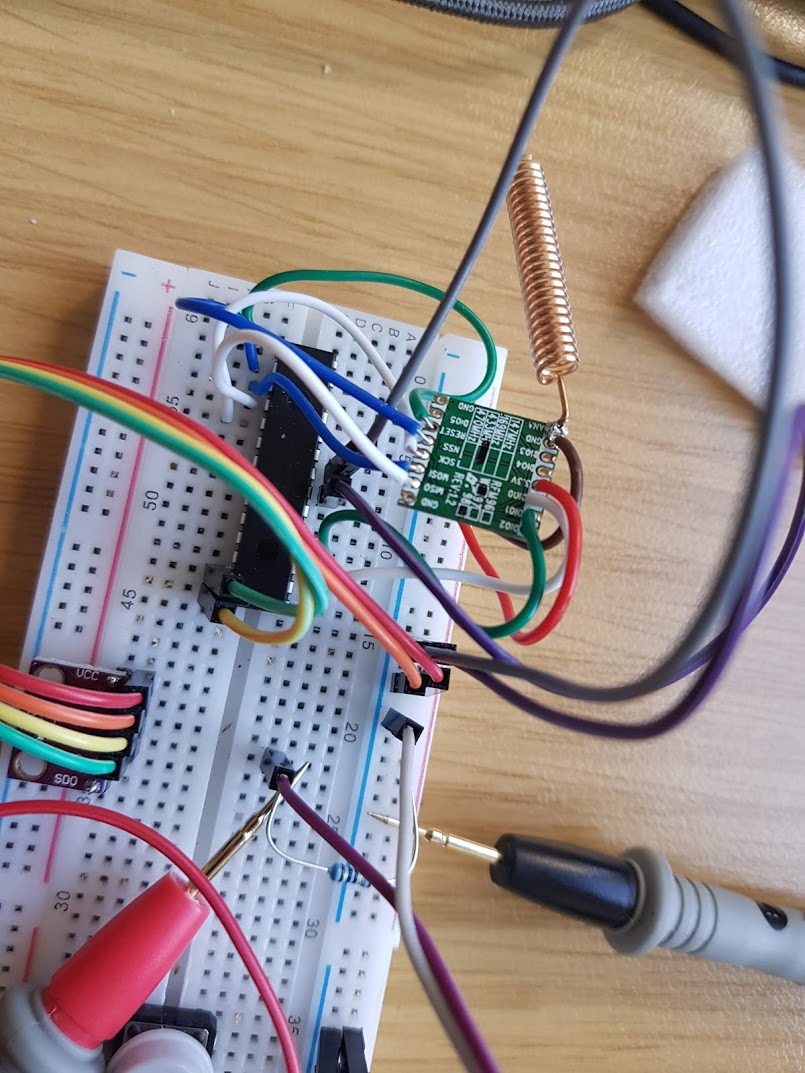
And I will connect the AGND and AVCC pins.
This works:
and there’s someone on here who can answer questions ![]()
1 Like
Thank you all for all the help. I really appreciate it. I will let you know about my results. Happy holiday everybody.
Summary:
- Connect AGND and AVCC
- Measure Current or Voltage over Resistance continuously and log it to file or similar
- switch to LMIC for TTN
There are low cost multimeters that will log to file via a PC application, the HP-90EPC for instance.
There are USB power meters that will give a running total of maHr, these can be handy, an example is the UM25C.
Alternativly use very low capacity LiPos, say 100mAhr or less, you dont need to wait so long.
1 Like
Hi. Recently I bought two SX1276 to work with 2 Arduino Mini and Pro to get started with my LoRaWAN nodes. Also, I received today my Heltex HTCC-AB1 which will be with a Raspberry Pi do work as a LoRaWAN 1 channel gateway. I suggest you use 3xAAA or AA. Could be better and easier to regulate from 4.5v and to handle with low power over time in your project.
I would try to reply to your circuit and test with an oscilloscope in a few weeks.