Strange output power with lambda62 module

Some constatations.

First one : RSSI returned by base station seems to be expected received level in dBm. This value is always (I have tried several distances between device and base station) RF power - free space losses. Of course, RF power measurement is done in lambda62 pin 1 with a level meter.

Second one : SetPAConfig and SetTxParams are set to emit 14 dBm. I have checked hexadecimal values sent to SX1262. I have done some other tests with 0 dBm. Only one difference : RSSI returned by base station is 14 dB lower.

Best regards,

JB

I will try as soon as possible. My spectrum analyzer should be sent back by Agilent next week.

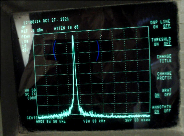
I come back. I have done some measurements with my HP 8592B.

LoRaWAN

Center 868 MHz, span 10 MHz

This measurement was done with a coaxial cable directly connected between Lambda62’s pin 1 and 2 (Rf output and ground) and when power output is set to 14 dBm. Of course, antenna was removed. Power was very similar to power I have found with my level meter.

I have checked my LoRaWan library and sent to serial console all transactions between CPU and SX1262:

set radio reset: ticks=7484
// GetIrqStatus $12 + NOP // RFU + Status
W1200
R0000
clear radio reset: ticks=7508
W1200
R0000
// SetSleep $84 + cold start + RTC timeout disable
W8400
W1200
R0000
W1200
R0000
// SetRegulatorMode $96 + only LDO used for all modes
W9600
// SetDIO2AsRfSwitchCtrl $9D + enable
W9D01
// SetStandby $80 + STDBY_XOSC
W8001
W1200
R0000
// SetPacketType $8A + LORA
W8A01
// SetDioIrqParams $08 + enable all interrupts
W080000000000000000
// SetRX $82 + single mode
W82000000
listen for entropy: ticks=71925
W1200
R0000
// ReadRegister $1D Addr 0819 + NOP (32 bits random number)
W1D081900
RCE4C999F
// ClearIrqStatus $02 + clear all interrupts
W02FFFF
// SetSleep $84 + cold start + RTC timeout disable
W8400
read entropy: ticks=71941 entropy=2677624014
W1200
R0000
OTAA is pending
add dither to otaa: ticks=72008 delay=1032
W1200
R0000
W1200
R0000
W1200
R0000
W1200
R0000
...
W1200
R0000
W1200
R0000
W9600
W9D01
W8001
W1200
R0000
W1200
R0000
W1200
R0000
TX power : 14 dbm
W8A01
// CalibrateImage 863-870 MHz
W98D7DB
// SetPaConfig $95 + paDutyCycle=2 + hpMax=2 + SX1262 + $01
W9502020001
// SetTxParams $8E + $0E (14 dBm) + 200 us rise time
W8E0E04
// SetufferBaseAddress $8F + TxBase $00 + RxBase $00
W8F0000
// SetRfFrequency
W863644CCCC
// WriteBuffer $0E
W0E00000F315CEE948A4D0457EF13000BA304000000A05C207F
// SetModulationParams
W8B07040100
// SetPacketParams
W8C000800170100
// SetDioIrqParams
W080001000100000000
// WriteRegister LoRa Sync Word MSB Public Network
W0D07403444
// SetTx
W83000000
tx begin
ticks=73124 freq=868300000 power=0  bw=125000 sf=7 size=23
W1200
R0000
...
W1200
R0000
W1200
R0001
Interrupt TX
W1200
R0001
offtime=100
W02FFFF
W8404
tx complete
ticks=73201
W1200
R0000
W1200
R0000
...
W1200
R0000
W8A01
W8F0000
W863644CCCC
W8B07040100
W8C000800FF0001
W080202020200000000
W0D07403444
WA082
W82000000
rx1 slot
ticks=78149 timeout=130 lag=2 freq=868300000 bw=125000 sf=7
W1200
R0000
...
W1200
R0200
Interrupt timeout
W1200
R0200
...
W1200
R0000
channel is ready
W1200
R0000
W1200
R0000
...
W1200
R0000
W8A01
W8F0000
W8636586666
W8B0C040101
W8C000800400001
W080202020200000000
W0D07403444
WA00A
W82000000
rx2 slot
ticks=79124 timeout=10 lag=3 freq=869525000 bw=125000 sf=12
W1200
R0000
W1200
R0200
Interrupt timeout
W1200
R0200
W02FFFF
W8400
W1200
R0000
W1200
R0000
...
W1200
R0000
waiting to retry OTAA
W1200
R0000
add dither to otaa: ticks=79910 delay=25861
W1200
R0000
W1200
R0000
...

R: read + hexadecimal data
W: write + hexadecimal data

Best regards,

JB

Problem solved.

I have bought 20 modules. 40% of them don’t send more than 0 dBm. 60% of them run as expected and send @14 dBm.

How does receive sensitivity compare?

I’d inspect one of your lower power units under high magnification for possible solder issues within the module, particularly the main IC and the RF switch.

Another thought might be wrong components in an RF network on some of them. Since you have a spectrum analyzer you could set one up with low power output in a closed-cabling (non-radiating) situation and frequency sweep it over several hundred megahertz. A good one should show networks optimized in the 868 and/or 915 range, one with a bad network might show a different shape or have its best performance elsewhere.

All modules have the same RX sensitivity. I will investigate, but I have checked solder issues with my binocular (20x). I haven’t found solder issues and I have tried to solder a coax before RF switch to check TX power, but without success :frowning:

I’d go with the sweep then.

Even if I had to create a software scalar network analyzer by using another as a receiver - which would mean I’d be seeing through the network of that one, too. But if the receive side was a “good” one seeing the difference between a frequency sweep of good > good and suspect > good might be informative.

Or do it manually with 50 MHz steps from say 600 - 1000 MHz.

You are actually driving both inputs of the switch, right? I found that with the receive side undriven I get better sensitivity than with no antenna connected, but much worse than I got by actually driving the receive side switch enable.

Yes, I drive both inputs of RF switch.