Pretty much every data sheet for standard LEDs will use 20mA for typical illumination levels …
Nah, this is a tiny SMD led that was barely glowing.
After removing the LED (or rather a resistor next to it, same effect) the current consumption didn’t drop much. The LED wasn’t what caused the battery drain. I misremembered in previous post - battery drain was around 2mA in deep sleep. With LED disabled it draws maybe 0.1mA less, this could be just measurment error. Perhaps this is some SoftRF error, will check it next.
0.1mA would definitely make for a very dim LED. Quick check on my primary supplier for surface mount LEDs, out of 216 mainstream options, 191 of them are suggested at 20 to 30mA.
You may want to see what IO you can turn off / high impedance / set high, as appropriate for their connections.
Hi, I’m here again!
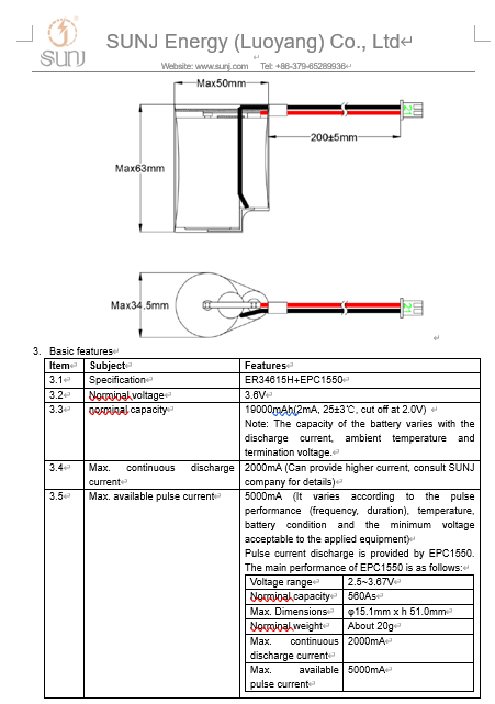
I’m doing several improvements to device, one of them is trying to use a lithium thionyl chloride (LiSOCl2) battery to extend lifetime. Appears that the unique voltage available to those kinds of batteries are 3.6V or 6V.
Theorically it’s fine because it’s basically the same nominal voltage as 18650 batteries, but difference is that a fully charged 18650 battery offers around 4,1-4.3V and my 19Ah LiSOCl2 batteries only output 3.71v in my multimeter.
I have connected a LiSOCl2 one to battery pins holder of TTGO T-Beam, but after pressing power button, board switchs on only for a couple of seconds, and then, switch off. Then I connected battery to 5V Vin pins of board and result is the same (but here pressing power button is not needed).
Measuring with a multimeter I think problem is that TTGO TBeam board requires a current amount higher than that such of LiSOCl2 batteries can deliver, because while board is booting voltage drops to 3.61V, and i think that when board detect votage drops below a certain value, it switchs off.
I think that is possible that voltage drops even more, but during a very short time lapse, which is unable to be measured by my multimeter (it can’t record peak values, only instant values).
I think that 19Ah value shown in battery is only a theorically mesurement of current, but in fact, those batteries can only deliver a tiny amount on mA instantly.
Using a step-up circuit to elevate voltage is not an option because that circuits have consumption even with output disconnected.
I attached a video that i think it shows clearly what i mean, replacing circuit board with a tiny dc motor.

I’ll back to 18650 again and I’ll put three of them in paralell, with 3A fuses between them and other fuse for circuit.
I’d expect much of the circuitry to actually run on 3.3V so it may well be the power management chip on this module and an LDO or Buck convertor are expecting 5v and aren’t able to cope, most typically by having to much voltage drop in processing before it gets to the actual circuit.
With a 3.6v battery I’d be mighty tempted to bypass the voltage regulation - I do that with some Pro Mini based devices, they start out on 2 x Lithium AA batteries at ~3.6V, quickly settle at ~3.4V and keep on working down to around ~2.7V.
Hi, thanks!, the TTGO T-Beam board has a 3.3V input, on DCD1 Bus and I could connect here the 3.6 V battery without problem, and board will power up pretty sure, but if I do that, I’ll not be able to deep sleep the board anymore, because AXP chip will not manage DCD1 current.
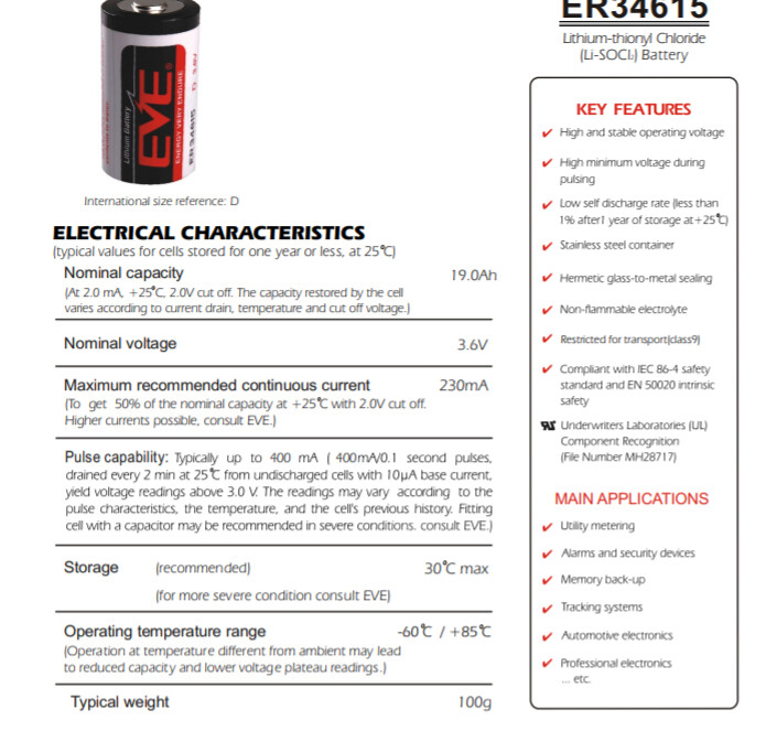
That is the total amount of energy stored in the battery, however this chemistry can only deliver a limited amount of energy at a time. Check the data sheets for the brand you are using for the peak load allowed. Also be aware drawing peak loads will deplete the cell sooner and you will only be able to get a small percentage of the total listed capacity from the cell.
Many thanks, is exactly as you said, I just find datasheet:
A well-designed LoRaWAN node can operate from these, but that doesn’t mean that the particular LoRaWAN node you have will do so. It may have excessive peaks of current draw.
If you have a scope, try powering it through a 1 ohm resistor (maybe with a capacitor in parallel) in the ground lead, and watch the voltage across the resistor with the scope. (You’ll need to have no other connections to the board while you do this)
No matter, problem I have is just the battery chemistry. Even I didn’t have those problem during board boot, I’ll sure have them when I need to activate certain devices connected to a mosfet relay IRF520 such I have attached to board. Those devices are activated by the relay getting energy directly from battery. They are only needed in special occasions but they need around 500mA of continous current, so I know that a LISOCl2 battery is not possible at all…
I can replace the battery with a 3-pack 18650.
in this case , Lisocl2 battery will work good with a super capacitor EPC1550 .