TTGO T-Beam V1.0 & OLED & deep sleep needs proper power design

Hi Verkehrsrot,

with my T-Beam V1.0 i discovered that i have a SH1106 display. Nothing dramatic that can´t be handled to get it to work.
But so far the display work as expected.
And even on sleeping the display is switched off by sketch and on after a time again.

I am using this at the moment.

It is Arduino stuff not native esp-idf. But it works so far for 15km to next gateway.
Not reliable on permanent base. But some packets strike thru. :wink:

So i think actively powering off the display from axp chip is different from “screen_off();”
Most of the I2C devices are able to put into “off” state or low power consumtion.
Otherwise with some soldering it should be possible to switch the power with a gpo and a transistor from the esp itself. Not clean but most power off you could get then.

with my T-Beam V1.0 i discovered that i have > a SH1106 display.

T-Beam doesn’t have a display on board. It has to be purchased separately. So there is no certain display, it depends on what you buy.

Hi, just in case some encounter the same issue, because of the issue of SSD1306 being “wired” on keeping line up on deep sleep while sharing the main I2C with AXP, I decided to move to the 2nd Hardware I2C on ESP32. I was initially unable to make it work, until I notice that my t-beam v1.0 AXP was outputting 1.72V on the DCDC1 ! After I set it to 3.3V (cf AXP library setVoltage…) at boot the second I2C on pin 13 and 14 works like a charm !

2 Likes

I can confirm that power down of an OLED SSD1306 on i2c bus #1 of TTGO Beam v10 will block the i2c bus, thus communication with PMU AXP192 is no longer possible and we get stuck in a chicken-and-egg problem. Thus, moving display to i2c bus #2 sounds like a reasonable solution, but is it possible to keep the hardware pins for direct 1:1 soldering of display to the TTGO header, without wires?

You can stil use th same position for VCC and GND but will have to wire to the pin 13/14 in deed, not a big issue, the screen stays at the same position. Although I would anyway not consider only soldering th screen to the pin for holding it, I’d rather go with a plastic case / 3D printed case… (like the softserial ones …)

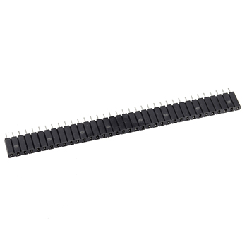
There exist female headers like the one below.
They fit standard Dupont type male header rows and have better, more firm contact than the average flat female header row connectors.

They make it easy to quickly attach and detach the display to the board.
Less suitable for mounting in a case because the display stands off farther from the board than when soldering the pins directly to the board…
Soldering the display (header) directly to the board can be usefull to mount the display while keeping it compact.

S36FMZ

hi,
could you post your code so i may try to revive my dead AXP chip please?

Hi Repherb,

Not sure what caused your AXP to “die”, but maybe I can help.

I recently brought mine back from a bad config using a Bus Pirate. The ESP32 is perfectly capable of sending commands via i2c to the AXP192, which put the board in a state where it can no longer be configured!

I own 2x T-Beam 1.1’s, and so I used the Bus Pirate to read configuration registers from the “good” board, then write those same values to the bad board. Here is a dump of the “good” values the T-Beam 1.1 was pre-configured with.

You can also use a second microcontroller, such as an arduino, to “inject” i2c commands onto the bus, instead of a bus pirate.

1 Like

The TTGO Lora32 V1 is not suitable for batteries.
Consumption does not go below 10mA
But there’s a way I’ve found

Hi guys, maybe a little late, but I had the same problem with TTGO LoRa32 (V1) deep sleep power consumption and I managed it by cutting the LDO from 5V circuit and by soldering the LiPo directly to LDO.
Fortunately the LDO is wired to 5V-circuit by a more or less good reachable single track coming from right top (on my picture) to the right top corner of pin 1 of LDO.
After this change CP2102 is powered only by 5V USB and working if USB is plugged. The on board LiPo-charger of course is not working. No problem for me, because I decided to use a discrete charging module with temperature tracking and batterie protection. But you may wire pin 3 of charger and pin 1 of LDO by a shottky diode - should work.
Deep sleep power consumption now is 900uA.

Cut

1 Like

Meanwhile i got a TTGO T-Beam v1.1. Could not yet spot any design changes in circuit. Running my paxcounter software, with a SSD1306 OLED display connected and soft-set to sleep mode, the TTGO T-Beam consumes about 8,5mA in deep sleep mode, while power of GPS and LORA chip is cut off by AXP192 PMU chip.

imho the design-change between V1.0 and V1.1 is an “active diode” that replaces the former fuse to protect the AXP from burning if you insert the battery in the wrong way.

1 Like

Did anyone here achieve lower power consumption than 8,5 mA with T-Beam 1.1?

Aliexpress descriptions say, V1.1 has (newer) Semtech SX1262 chip, while V1.0 sports the SX1276/1278. Since the chip mode is covered by metal, i could not verify this. SX1262 is NOT working with (current) LMiC, but my “V1.1” device does - so it must have SX1276…

1 Like

Here you can find more information concerning the different versions

2-3 mA is reported here:

and 600uA is reported there:

Tested:

With a T-BEAM v1.1 (with LORA chip HPD13 / SX1276), AXP192 in shutdown mode, LORA and GPS power cut off by AXP192, and a SSD1306 OLED connected to I2C pins and in sleep mode (because cutting off power of OLED would block i2c bus) i see

  • 1,2 mA battery current, if esp wakeup is set by GPIO
  • 0,9 mA battery current, if esp wakeup is set by timer
  • 40-50 µA battery current, if esp is powered off by AXP192
1 Like

Thanks for your very clear feedback.
How do you wake-up once powered off by AXP192 ?

Wakeup can be triggered by ESP32 (using timer or GPIO button), or by AXP192 (using PEK button).

Unfortunately on TTTGO T-BEAM boards the I/O ports of the AXP192 chip are not connected to ESP32, thus a wakeup on GPIO triggered by AXP192 is not possible, what means that the sleep mode of AXP192 cannot be used.

Hi repherb,

I uploaded the sample script for the AXP192 chip from Github and bricked my TBEAM :frowning:
Luckily I noticed that if I held the PWR button down the red led would sometimes glow dimly. So I modified the code from Github and reflashed, setting the line 18 to “.DCDC3 = 3300”, which I think sets the power for the ESP32 to 3.3v instead of 0 in the default code.

Hope thats help someone. @roleohibachi pointed me in the right direction. That;ll teach me to blindly upload sample scripts :slight_smile:

…and never set it to values greater than 3300…

1 Like