Hi, my problem is with a accelerometer GY-521 instead a display, but i’m in the same case.
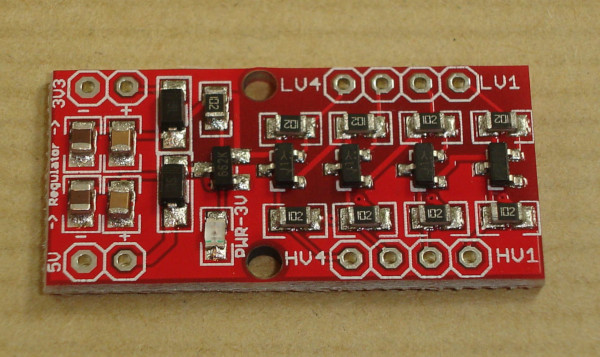
then, if i understand well hardware solution of @stickbreaker, i need to connect +3v3 and -3v3 connectors of BD-LLC in the image i uploaded to +3V3 and GND of T-Beam Board, and then is needed to connect LV1 to VCC of accelerometer.
GND of accelerometer is shared with GND of BD-LLC connected to GND of Board. ¿isn’t it?
Thanks!
That picture is from a level converter, not GY-521.
If you are having similar issues with your accelerometer as the ones described for the display then only one of the solutions mentioned below (replace display with your I2C device) will solve the issue.
Yes, picture is of a level converter, i mean that problem with oled display mentioned in this post is the same than i have with a accerometer connected to I2c.
Gy-521 works well at 3.3V, but after TTGO T-BEAM board wakes up of deep sleep not works if i previously disconnect DCDC1 with AXP library: setPowerOutPut(AXP192_DCDC1, AXP202_OFF);
Problem mentioned in this post is that after wake-up of deep sleep i2c not work, and @stickbreaker posted that is possible to fix it with a BD-LLC isn’t it?
It appears you are posting in the wrong topic nor are you providing any links.
Also @stickbreaker is not a user on this forum.
So you know very well that a level converter is not needed, but nevertheless confuse other users with a picture of a level converter wasting their time.
I am sorry for the apparent confusion, it is not my intention to waste anyone’s time, what I mean is that the i2c bus of the TTGo T-BEAM gets stuck after waking up, in this post you are talking about that it is not possible turn on the OLED screen again. I have an accelerometer connected to the 3V3 pin instead of an OLED screen. And my bus i2c get stucked after wake up from deep sleep too.
Github stickbreaker user in link posted previously by @Verkehrsrot (i don’t want to repeat urls previously posted) uses a BSS138 to avoid the problem. The image I uploaded is a 4 Channel Logic Level Shifter using BSS138.
The issue described in this topic is that it is not possible to power up the display again after it has been powered down by the PMU (caused by the display incorrectly pulling the I2C lines low when powered off).
A different issue (‘B’) with problems with ESP32 I2C bus after waking up from deep sleep is described here: Switch off devices attached to board to save energy
That issue appears to be related to configuration of (role assignment) of ESP I2C GPIO pins.
Both issues seem to be unrelated (even while both are related to I2C and both issues become visible after waking up from deep sleep).
Your problem with the accelerometer seems to be issue B related (which is not the subject of this topic).
Sorry for that! other post was created for me, and effectively, i was in problem to configure correctly GPIO Pins, because what i want was manage power with AXP202 library. Finally i did it, now i can choose voltage on DCDC1 pin, and connect/disconnect Lora/GPS etc. thanks to @Verkehrsrot, but, then i think ran in problem of this post. If i include this line before deep sleep:
setPowerOutPut(AXP192_DCDC1, AXP202_OFF);
bus i2c not recover from deep sleep, and is impossible to power up DCDC1 pin again. So i think my problem is the same described above in this post, if not, sorry again for that.
I can understand that the problems look similar and they actually may be the same (see above). Both are ESP32 and I2C related and both become visible after waking up deep-sleep.
If your problem is the same as the subject of this topic it can be solved by using one of the three mentioned solutions (using the MOSFET solution described in the GitHub article is actually just a variation of using an I2C bus isolator chip).
The simplest of the three alternatives is to define a second I2C bus for the display (and/or other I2C devices) on different GPIO ports/pins. That solution does not require any additional hardware and will use only little additional memory.
Just to add in something we have noticed at least with our V1.0 Tbeams. The 3.3V power rail exposed on the headers actually only outputs 1.8V’s on startup. We had to then communicate with the PMU over I2c to actually give us the required voltage of 3.3V. No massive biggie, but we had a bunch of students using Xbee’s that appeared non-functional at first, until we located the source of that issue!
Hi!
I’m new to both ESP32 and Lora, but very interested in what the possibilities they offer.
I’ve been searching randomly for a good, cheap board for testing range etc, and later consider setting up a gateway at home which I can reach from my boat.
I’d like to use a 18650 battery (or similar) and TTGO T-Beam ESP32 was the first thing I found which also had a battery holder. When I learned about Lora I read 5+ years of battery life, but it seems like you’re lucky with 5 days with a lot of the current devices, as long as they don’t catch fire.
Is the TTGO T-Beam the way to go? I like that it has GPS and display, which is nice for testing, but for a permanent sensor setup, I’d like something as simple as possible with Lora + I/O for a few sensors like temperature and wind etc.
T-Beam is good for evaluation, but not suitable for production use.
There is a broad market for sensor boards. You need to get a clear view on your requirements.
You may take a look at MCCI’s boards. They are on high level of serious engineering.
China products often have a lifecycle of a few months only, then often disappear from the market or version changes. And there are copies with issues etc.
It would be “production use” only for hobby/home automation. So if it can handle that, I’m interested.
I like the idea of putting a 18650 battery in the holder, but I am a bit afraid of fire, reading that some TTGO devices has actually caught fire when charging.
It would be nice with solar panel charging etc, but absolutely not necessary. Mainly I think I’d use the battery for testing range, and as a “UPS”, otherwise always keep it plugged in, charging.
But if I understand this thread correctly, it’s only the included display that has issues?
The battery circuit failure issue was so far seen only with a certain TTGO board. But it shows what can happen. Every TTGO board seen so far had a new or modified circuit for battery charging. Currently they use a dedicated pmu chip AXP192. If you let those boards charge a 18650 in your home unmanned, you take the full risk. Those boards are development units, not products, and they have CE declaration. The supplier nor the importer will pay for any damages, and perhaps your insurance won’t, too.
If you take the risk, at least be sure that you get a 18650 cell with integrated pcb for overheating protection.
I use metal security boxes as supplied e.g. by robbe.com to operate my china boards with Lipos to mitigate the risk.
Myself, especially for projects that will be used in locations which are not regularly monitored, I much prefer to use Alkalines. If the project is designed right you will get a long battery life. Alkalines are not expensive, those from Ikea are very reasonable.
Do you think if is posible to connect a 3AA battery pack directly to battery holder connectors of ttbeam board, or will be needed a voltage converter?
Full charged li-ion 3.7v battery outputs around 4.2v, and full AA battery pack i think outputs around 4.8v.