Wow, that’s awesome work. The gnat is amazingly small. Does it require an external antenna for the GPS, or is there an internal patch? Personally, I’m really interested in the grasshopper model for a project I’m working on. Ive only skimmed through the docs so far, but it appears that it also has very well thought out low power modes for battery operation. One question I have is about the USB interfaces on all of these, doesn’t that add a fair amount to the power requirements, or is extremely low power as well when it’s not being used? Forgive me if I’ve asked a stupid question here.
The USB peripheral does indeed use a lot of power relatively speaking, but only when the USB cable is connected. There is a USB connect detect built into all of the board designs such that the USB peripheral is disabled when no VUSB is detected. In this way we can achieve the lowest power inherent in the Murata Type ABZ (CMWX1ZZABZ-078) module.
So for Grasshopper, the sleep current (once the power on led is disabled) is ~2.1 uA, ~1.65 uA for the L082 STOP mode (with full retention, 5 us wakeup) plus ~0.5 uA for the NCV8170 LDO.
For the LoRa SensorTile (AKA Cicada) this is ~8 uA since there is a battery charger and 16 MByte SPI flash as well as some sensors on the board. The Cricket asset tracker is a little more (~12 uA) since the 8 MByte flash uses ~2 uA less power but the GNSS RTC backup uses ~10 uA more or so.
The Gnat and longCricket were designed to minimize power usage even further (check the Tindie product pages for a fuller description) so that each uses as little as ~2.5 uA when the L082 GPIO powering GNSS RTC backup is disabled while the BMA400 accelerometer continuously monitors for fast wake-on-motion.
This is probably more than you wanted to know…;>
3 Likes
This seems to be perfect for my application. I’ve assets which move within a fixed radius (say 2km) in an industrial environment. The location of these assets needs to be tracked on a real-time basis, and this information will help in planning and scheduling their movement so as to improve the process. I’ve a couple of questions related to these devices:
- Do they withstand industrial outdoor environments?
- What is the accuracy of devices in meters?
Thanks in advance.
The data sheet says 2.5 meter CEP and by my experience two meters is about right.
I would put either of these in an IP67 container to protect against water but otherwise they should work as well outside as any consumer product (-20 C < T < 85 C).
Hi!
As an owner of a couple of Gnat boards I would just like to say thank you to @onehorse and @GrumpyOldPizza for creating the board and Arduino core with examples. Getting started with the modules is really easy and painless.
Right now I’m trying to take the next step from “getting started” and struggled a bit with connecting an st-link for swd debugging. It turns out I needed to call the STM32L0.swdEnable() function in setup(). Is this mentioned anywhere on the tindie/github/hackaday-pages? If not, I thought it might be worth mentioning it here to make it googleable. 
Thanks for the kind words; we are glad you are finding the Gnat useful!
I usually use the Arduino IDE via USB to program these as intended but I have used an ST Link V2 to program a Gnat once just to make sure this as possible and I am sure I didn’t need to call such a function. In fact I have designed many custom devices with the CMWX1ZZABZ without USB that use Thomas’ system layer + Arduino core and the same ST Link V2 and have never had to do anything special to make them work. So this comes as somewhat of a surprise to me. Maybe Thomas has an explanation…
Yes that is correct.
Problem at hand is that for debugging (SWD) in STOP mode the main clock is kept alive. That is a huge power drain if you are running something in a normal setup. So if you call STM32L0.sleep() or STM32L0.deepsleep() the code per default disabled SWD (GPIOs, plus a bunch of other things) if neither STM32L0.swdEnable() or STM32L0.swdDisable() had been called.
Ah! That makes sense. The sketch i had flashed when trying to connect with st-link util was using sleep mode. Thanks for the info.
Yes, this was due to sleep mode disabling the SWD pins. I also use the USB for upload, but using SWD also enables remote debugging.
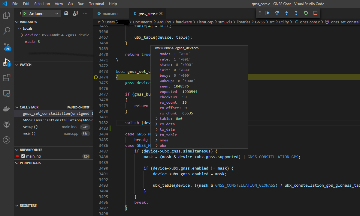
I am using VS Code with the Arduino plugin for my coding, I quite like the syntax highlighting and intellisense/auto complete functionality as well as being able to follow the code structure and quickly peek at function definitions and so on. As this code base is not too heavy on documentation, I find that very useful. And also because I’m a pretty crappy programmer. 
Now that I got remote debugging to work, I think the VS Code environment will be even more useful. I have not seen the same functionality in the Arduino IDE to set breakpoints, step over/into/out in code and inspect variables/objects and registers while running live on the device.
Interesting. Debugging via the Arduino IDE is serial monitor only;>! But this works for me…
Is VS Code freeware? Does it run on WIndows 10?
I have used Eclipse for programming the MAX32660 and I learned to appreciate stepping and breakpoints, etc The problem I have had with adult tool chains like Keil and Eclipse was that I could never make it through the 27-step install process without hitting a brick wall. Or once I got an installation that kinda sorta worked (usually through an ST workshop) I had no idea how to actually use the thing. Way too complicated with a million configuration windows. The magic of the Maxim 32660 Eclipse programming environment is that all of the configuration knobs are more or less set correctly and I was able to make this work.
I prefer the Arduino IDE since it is so easy to use. This allows me to focus on the application and rapidly get a device working for testing and production. But this is only easy with a robust, memory- and power-efficient system layer underlying the Arduino overlayer. One that avoids race conditions, memory leaks, and with proper work arounds for the inevitable errata, etc. This is what Thomas’ Arduino core provides.
Still, I see the benefit of traditional debugging. If VS Code is easy to set up and use, I might like to try it out…
Freeware - Yes. Open source, a variant of MIT licence. Distributed compiled version as freeware.
Windows 10 - Yes, that’s how I run it.
Easy setup - Yes to get started. Enabling debugging on the STM32L0 core was a little bit quirky for me.
To get started, just download and install VS Code. Install the Arduino extension from the Extensions tab. Requires Arduino to be already installed. You will need to run an initialization for arduino projects that creates a settings-json for each project/directory. That far it has been smooth sailing for me.
For debugging, hit ctrl+shift+d → create a launch.json file → C++ (GDB) → Add configuration (bottom right) → Arduino.
This creates a boilerplate debugging setup. I needed to set the path to openOCD and set config arguments, I’m sure there are more elegant ways to configure this:
“debugServerPath”: “C:/Program Files (x86)/openocd/bin-x64/openocd.exe”,
“debugServerArgs”: " -f interface/stlink-v2.cfg -f target/stm32l0.cfg",
The stlink-v2.cfg sets the debugging link, stm32l0.cfg sets the mcu type. Adjust as needed.
I needed to change the “sketch” name in the arduino.json file to BMA400.cpp, as the compiler picks the first cpp/ino file in the folder as the compiled .elf name. As far as I have seen, that does not affect anything else. Again, it is possible there are more elegant solutions.
That should be enough to start debugging. You can compile and upload from the interface via usb (to also power the board) while connected with the st-link and then hit F5 to start debugging and set/change breakpoints while the code is running.
There is some more info at the extension webpage:
Some variables are optimized out, and the optimizer also causes some unintuitive jumps while stepping. I have experimented with creating an -o0 option in the boards.txt file for the Arduino core. I needed to also add the flag -fomit-frame-pointer to make that compile, as well as changing the following lines in (…)\Arduino\hardware\TleraCorp\stm32l0\cores\arduino\HardwareSerial.h :
virtual void begin(unsigned long) = 0;
virtual void begin(unsigned long baudrate, uint32_t config) = 0;
virtual void end() = 0;
where I added the “= 0” at the end.
That seems to be working pretty well so far. Some libraries are distributed already compiled from source that is located in folders that don’t exist on my machine. I’m sure you could recompile them to sort that out, but I have just avoided following the code into these parts of the core so far.
I hope this write up saves someone a little bit of work setting it up.
For other platforms (AVR, ESP) I use the PlatformIO plugin in VS Code. Their library management setup is excellent, keeping a separate set of libraries for each project. I have not seen anyone using it for the STM32L0 core yet though, I think that requires a bit more setup.
2 Likes