We’ve built some nodes using this example. I think more people did and probably most common sensors that fit inside the memory have already been connected to it by someone. A version with a DS18B20 works and we’re looking for other sensors to connect. The HTU21 shown in the example is next. Surprisingly there are hardly any ready to use sketches around.
This combination pro mini/rfm seems to be the cheapest possible node useful for relatively simple use cases. I think many less complex use cases get stuck on the still high price tag of available nodes. So ultimately I aim at making some pcb’s that could result in a working node with a price tag of a little over 12,50 (not counting the batteries and casing). But that’s something for a different topic.
To support that I’d like to build and share a library with ready to use sketches for as much sensors as possible. Does someone has something to share?
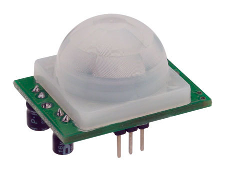
I added a basic PIR sensor example to the github repository. This is pretty straightforward and not very clean. It does detect motion but in order not to tamper with the duty cycle mechanism it always sends when a message is scheduled. I think it would be cleaner to make sending dependent on if there is something meaningful to send, but I don’t see a way doing so without going too deep into the LMIC mechanism.
Does anyone have a suggestion what would be the pretty way?
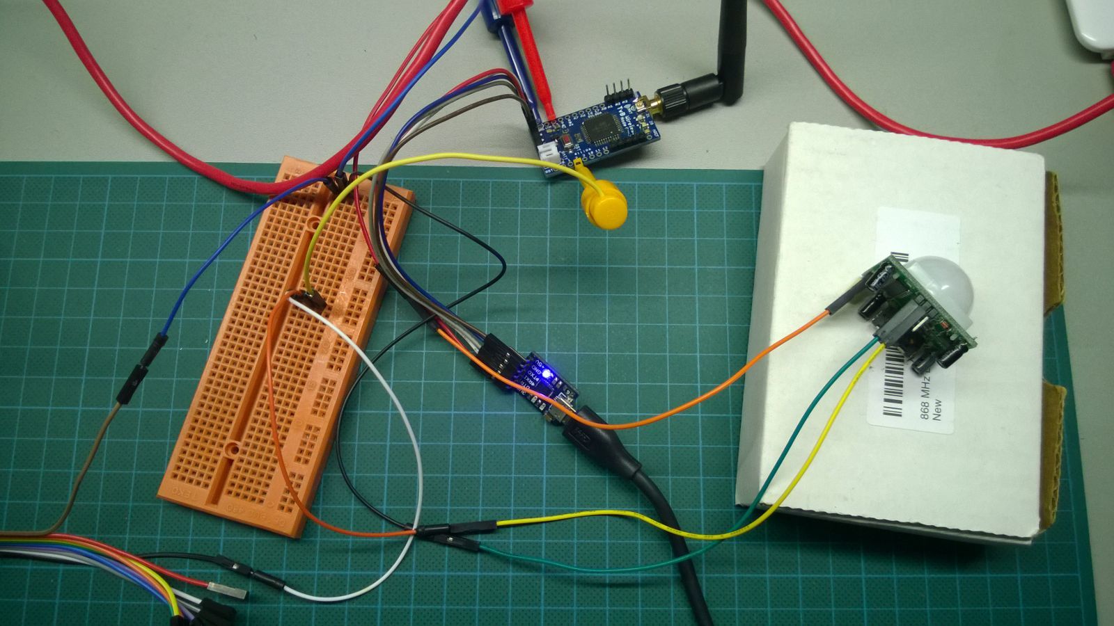
I did the same a few day’s ago and hooked up a PIR to one of my modules.
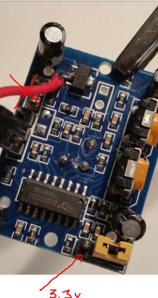
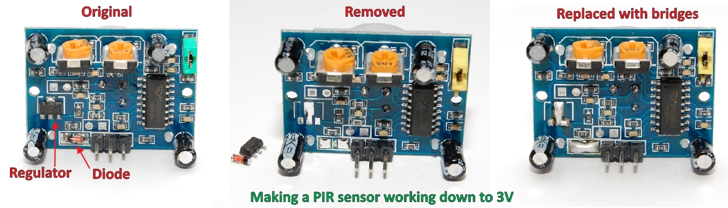
I don’t think you have to solder a wire to bypass the dc converter,
…connect your 3.3v (form Arduino) to the free pin near the jumper. Click on the picture to see the red arrow
…my experiment, it detects motion and sends a message. I’m fine tuning the timing and try to solve some code issues.(Orange wire 3.3v connected to PIR)
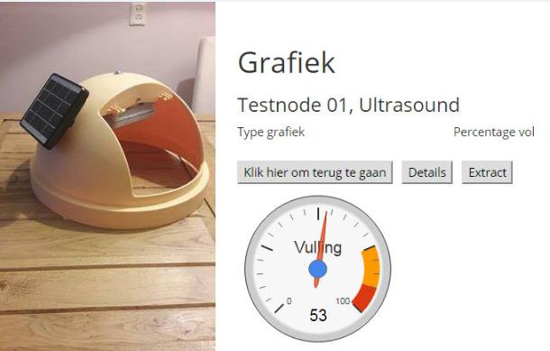
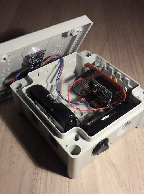
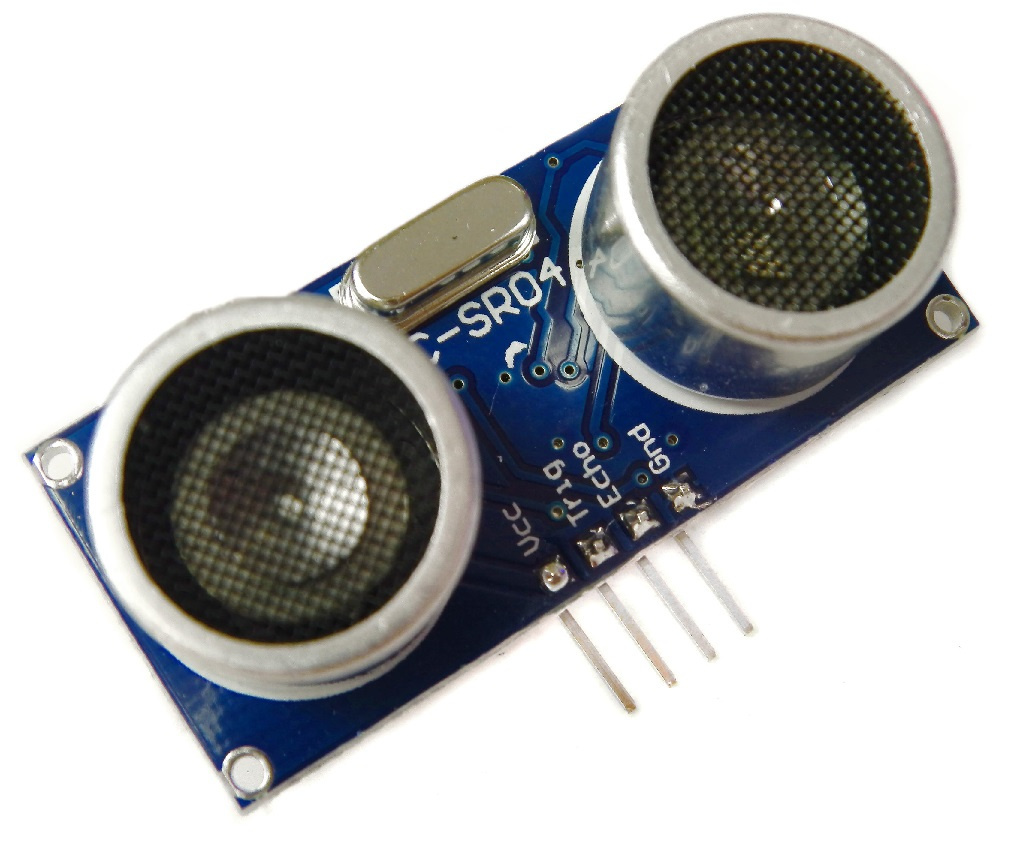
I just added the code for the SR-04 sensor to the github repository. That’s the same sensor as used in the yellow trash bin shown above.
Imporant: for most applications it’s better to buy an SR-04+ which runs 3.3v instead of the 5v for the normal SR-04. If you want to use the SR-04 anyway it’s best to use 4x1.2v batteries and power the SR-04 with it. In that case you can also power the arduino on the RAW pin with it while the signal pin could be a straight connection between SR-04 and arduino. Luckily you don’t need stuff like level converters for the signal. The battery usage proved not to bad after all, if I recall it right it was somewhere between 10 and 35mA depending if it was sending or idle.
Nice work! It looks like the wiring is different, but that pretty likely since there is no real reason to choose for a certain wiring. Probably a lot of more different wirings also exist… Perhaps we should just deal with it by adding something like a pin-layout-string to the code. By doing so we only have to copy/paste a single line instead of renumbering a block of code, which is annoying work and also frustrating because of potential typo’s.
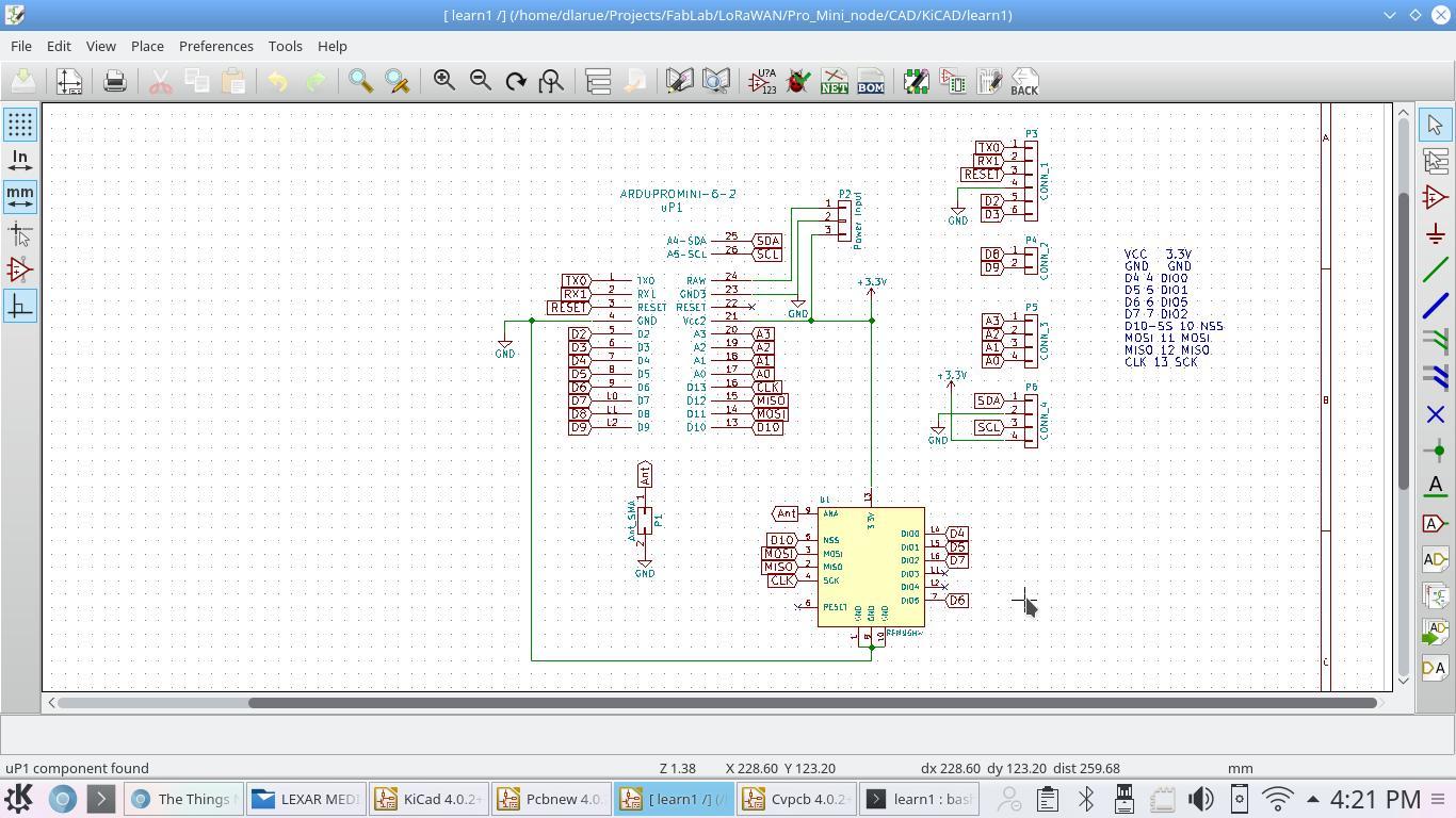
I noticed in your mail that you do use some RFM pins that are not used in my version. Could you please send me a working sketch so I can check which values are needed in such a string? Or could you test the ttnmapper sketch on my github to see if it works on your node when you renumber the pins?
// Pin mapping
// These settings should be set to the GPIO pins of the device
// you want to run the LMIC stack on.
//
lmic_pinmap pins = {
.nss = 10, // Connected to pin D10
.rxtx = 0, // For placeholder only, Do not connected on RFM92/RFM95
.rst = 0, // Needed on RFM92/RFM95? (probably not)
.dio = {4, 5, 7}, // Specify pin numbers for DIO0, 1, 2
// connected to D4, D5, D7
};
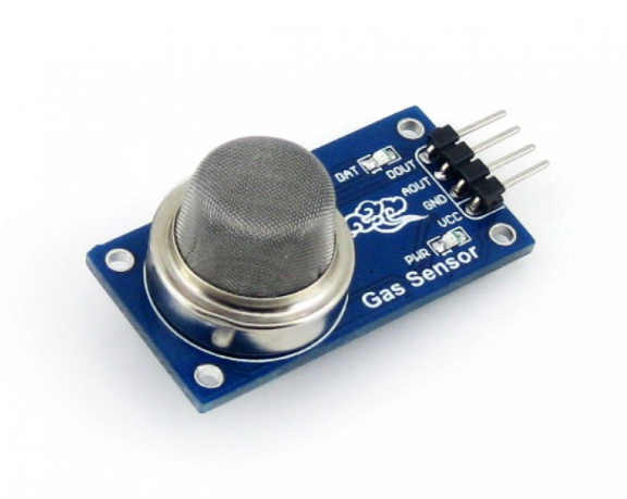
added code for the MQ135 gas/air quality sensor. It takes between each message a maximum of 100 measurements and sends the average value.
A few notes;
the readings of the MQ135 require some interpretation. See this and this
MQ135 sensors require quite some power. A 5v power supply instead of batteries is recommended. You can use this to power the RAW of the arduino. Theoretically, because for some reason my node rejected to transmit. The RX led flashed more brightly and longer than during ‘good’ transmissions, and this is the same behavior i saw with battery powered nodes with a close to empty battery. Still the power supply seems heavy enough though.
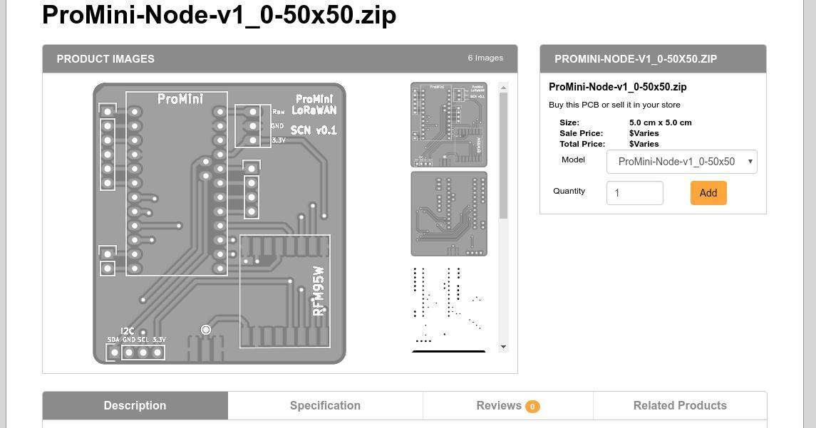
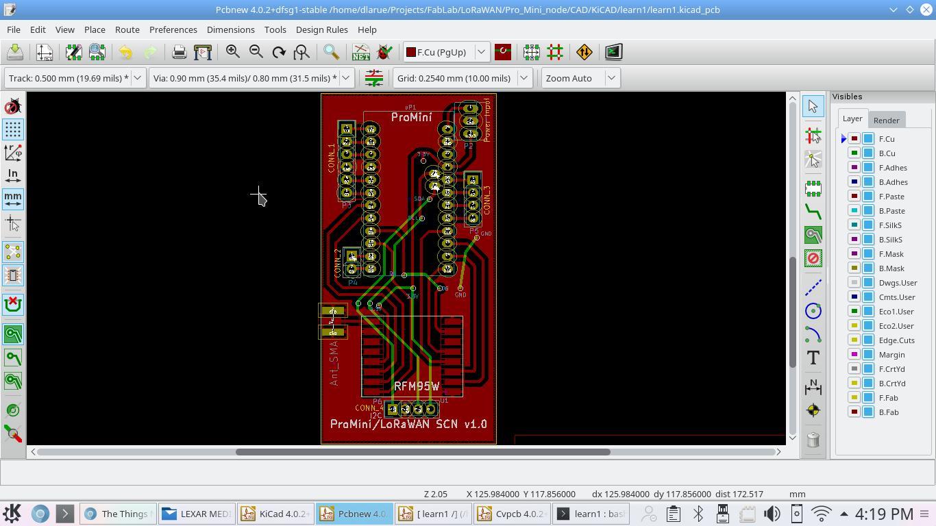
I also resized the board so we can get them 10 for $15 from DirtyPCBs.com with generally the same 2+ week turn around time as OSH Park. Change the board thickness from 1.2 to 1.6 after you select the order. My first boards were a pinch small for the SMA edge mount antenna connector and required epoxy to make sure they were strong.
ok, I updated the link so it should be ok. I resized the board so it fits their cheapest size constraints for 10 boards $15 for 10. Make sure you see a price like that or you might have to fiddle with an option. I go with the +/-10 and got 10 boards for ~$15. And remember to set the thickness to 1.6mm instead of the default 1.2.
That’s great @sa5bke and I’m just pleased others are finding them useful too. There is some extra space in one corner off of the power connector and I’m thinking of doing some revisions with some circuitry options there.
I would love to hear of options people would be interested in along with a schematic of the circuit or links to them. I’m willing to put the time in to develop the PCB with those options if you’re willing to order and test them.


 <img
<img