Big ESP32 + SX127x topic part 3

My TTGO paxcounter V2.1 finally works - i can confirm these settings (Arduino IDE):
Flashed with board setting “TTGO LoRa 32-OLED V1” (there was no other TTGO Board preset)

const lmic_pinmap lmic_pins = {
    .nss = 18,                       // chip select on feather (rf95module) CS
    .rxtx = LMIC_UNUSED_PIN,
    .rst = 19,                       // reset pin
    .dio = {26, 33, 32}, // assumes external jumpers [feather_lora_jumper]
                                    // DIO1 is on JP1-1: is io1 - we connect to GPO6
                                    // DIO1 is on JP5-3: is D2 - we connect to GPO5
};

I’m now having problems with power supply, when connecting a powerbank (USB) it works like a charm,
but when connecting a Battery to the battery connector there are massive dropouts - see the counter, it should send each 10 seconds:

image

I’m using this battery (which was recommended for the TTGO board) and it should be fully charged:

Is that battery too weak? Any other recommendations?

PS: no success at all with my Heltec V2 - I assume it’s either not the board as expected or it’s damaged … :confused:

To prevent further confusion, that is not the real name of your board.
The correct name of the board is TTGO LoRa32 V2.1-1.6 like shown below.

6

LilyGO is not very consistent in their naming of this board series.
The board’s model name is actually TTGO LoRa32, also referred to as ‘T3’ which is confusing.
V2.1 is the version of the model, while 1.6 is the revision number of this model version. Again confusing due to the double ‘version’ number. ‘TTGO LoRa32 V2.1 rev1.16’ would have been easier to understand.

ESP32-PaxCounter is the name of software that came probably installed on it.
There is a dedicated topic for PaxCounter: Wifi/BLE Paxcounter Project with ESP32 boards

thanks for your info - btw. do you know if there’s also an Arduino (IDE) version of paxcounter?

No there is not. To my understanding PlatformIO is used because the Arduino IDE is much more limited, lacks important features and is much less productive.

1 Like

Please properly format code and logs in your posts, see: How do I format my forum post? [HowTo]

To print RSSI and SNR for acknowledgements (ACK) independent from if data was received or not, do the following:

In the original code, from the if (LMIC.dataLen) { ... } code block remove:

u8x8.setCursor(0, 1);
u8x8.printf(“RSSI %d SNR %.1d”, LMIC.rssi, LMIC.snr);

And place it in a separate if statement after (not within) that code block as follows:

if (LMIC.dataLen) {
...
}
if ((LMIC.txrxFlags & TXRX_ACK) || LMIC.dataLen) {
    u8x8.setCursor(0, 1);
    u8x8.printf(“RSSI %d SNR %.1d”, LMIC.rssi, LMIC.snr);
}

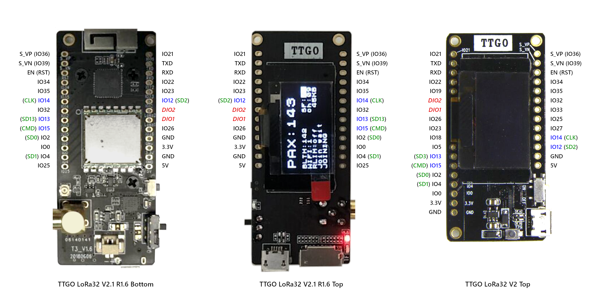
TTGO LoRa32 V2.1 rev1.6 versus TTGO LoRa32 V2.0 pin layouts

A while ago I made a comparison between the pin layouts of TTGO LoRa32 V2.1 rev1.6 and TTGO LoRa32 V2.0. There are important differences and a comparison was not available from LilyGO.
The layouts are included below in png and pdf formats.
Blue labeled pins are GPIO ports for the JTAG interface. Green labeled pins are GPIO ports used for the SD Card. Red labeled pins are LoRa DIO ports that are not connected to GPIO ports (and require explicit wiring to a GPIO pin when needed).

1

PDF: TTGO LoRa32 V2.1 rev1.6 versus V2.0 pin layout comparison rev1.1.pdf (2.2 MB)

UPDATE:
Different from what the above comparison says DIO1 and DIO2 on the TTGO LoRa32 V2.1.6 (V2.1 rev 1.6) seem to be already wired on the PCB.

3 Likes

Hi i have it now this way
indent preformatted text by 4 spaces

case EV_TXCOMPLETE:
            Serial.println(F("EV_TXCOMPLETE (includes waiting for RX windows)"));
            u8x8.drawString(0, 5, "EV_TXCOMPLETE");
            Serial.println(LMIC.rssi);
            digitalWrite(BUILTIN_LED, LOW);
            if (LMIC.txrxFlags & TXRX_ACK)
              Serial.println(F("Received ack"));
              u8x8.drawString(0, 5, "Received TACK  ");
            if (LMIC.dataLen) {
              Serial.println(F("Received "));
              u8x8.drawString(0, 6, "RX ");
              Serial.println(LMIC.dataLen);
              u8x8.setCursor(4, 6);
              u8x8.printf("%i bytes", LMIC.dataLen);
              Serial.println(F(" bytes of payload"));
                            }
            if ((LMIC.txrxFlags & TXRX_ACK) || LMIC.dataLen) {
              u8x8.setCursor(0, 1);
              u8x8.printf("RSSI %d SNR %.1d", LMIC.rssi, LMIC.snr);
                           }  

that doesnt work
ill think the if is not fullfilled, if i remove the LMIC.txrxFlags &
there is a line on the display rssi o snr o

Well, that should work but as said before only when you receive a downlink message (with ACK or data), which apparently you are not receiving.

Are you familiar with the details of downlink messages? If not then better start learning about the LoRaWAN protocol first.

The ‘SNR %.1d’ above makes little sense because SNR is an integer (int8_t) and not a float.You therefore should change it to ‘SNR %d’ instead.
But be aware that this is not the reason why both RSSI and SNR are not printed.

1 Like

the sreens says “recieved ACK”, so ill asume the node received an ack.

how can i debug to see if actually an ACK is recieved ?

btw i am using this code from gtihub:

today i searched some more, it looks like there is no ack sending to the node.
i see no download arrows if i look in the gateway, only upload.
i i test the with downlink i see messages with a dowload arow, the node doesn’t doe anything with it ill think.
i don’t see the rssi either after a download form the gateway.

i think there is something fundamentaly wrong with my code.
can some one help me with this ?
the code i use is above.

I don’t have an Arduino IDE to check at the moment. But if I remember correctly, the XTAL frequency is mentioned in the Tools menu where you select and cofigure your board.

Also from memory: The ESP-IDF framework provides a function to estimate the XTAL frequency and the Arduino framework uses it to simplify usage. The default in ESP-IDF however is to set it explicitly.

If you somehow configure the XTAL frequency incorrectly, serial communication will only transmit gibberish. So it’s quite obvious if it’s incorrect and therefore it can’t be the cause of LMIC timing issues.

Also from memory: The ESP-IDF framework provides a function to estimate the XTAL frequency and the Arduino framework uses it to simplify usage. The default in ESP-IDF however is to set it explicitly.

That’s right, the actual clock frequency is by default setting in arduino-esp32 guessed based on an internal 8 MHz clock source, using ESP-IDF option “Autodetect”. As long as this works, selection of 26 vs 40 Mhz crystal should not have any impact.

https://docs.espressif.com/projects/esp-idf/en/latest/api-reference/kconfig.html#config-esp32-xtal-freq-sel

No gibberish so that is probably unrelated then, but I see no reference for XTAL frequency.

In the Arduino IDE Tools menu (and in the ESP32 Arduino Core files) I only see settings for CPU frequency and SPI frequency but no explicit setting for crystal frequency.

If I interpret the list of possible CPU frequencies it appears like WiFi/BT will only work for CPU frequencies 80MHz and up and lower frequencies can be set only with 40MHz XTALs (but not sure if those assumptions are correct).

capture%202019-10-22%2015%C2%B714%C2%B737

Related thread (external): ESP32 40Mhz vs 26MHz XTAL

(But does not give much details about differences.)

(Ah, I overlooked @Verkehrsrot’s last post.)

I think that the menu entry mainly configures the clock multiplicator/divisor and that Bluetooth and WiFi require a speed of at least 80 MHz. The XTAL reference is somewhat misleading.

Whoever designed the the Heltec WiFi LoRa 32(V2) board definition probably knew that this board only exists with a 40MHz crystal and designed the entries accordingly:

  • 240 MHz = 40 MHz × 6
  • 160 MHz = 40 MHz × 4
  • 80 MHz = 40 MHz × 2
  • 40 MHz = 40 MHz × 1
  • 20 MHz = 40 MHz ÷ 2
  • 10 MHz = 40 MHz ÷ 4

Compare this to the Heltec WiFi LoRa 32 board, which has a 26 MHz crystal.

  • 240 MHz = 26 MHz × 9
  • 160 MHz = 40 MHz × 6
  • 80 MHz = 26 MHz × 3
  • 26 MHz = 26 MHz × 1
  • 13 MHz = 26 MHz ÷ 2

The higher frequencies are approximations only and are off by 2.5%.

1 Like

I actually didn’t notice but the Heltec V1 and V2 indeed have different crystals.

I was not aware before that ESP32 can be used with CPU frequencies lower than 80MHz (it’s just that WiFi/BT are not supported anymore then).
Have not been using Arduino IDE for a long time and PlatformIO does not show these values in a nice dropdown. Previously those lower frequencies were not listed (not yet supported).

The low CPU frequencies appear interesting for low-power applications.
Do you have any experience with using the ESP32 @ 10MHz (or 13MHz)?
Does it draw substantially less power than the default 80MHz?
Do you possibly have any comparison figures available?

Crystals used on some popular ESP32 LoRa boards:

Most of them use a 40MHz crystal.

Board Crystal frequency
Heltec WiFi LoRa 32 V1 26MHz
Heltec WiFi LoRa 32 V2 40MHz
TTGO LoRa32 V2.0 40Mhz (integrated in ESP32-PICO-D4)
TTGO T-Beam V0.5 40 MHz

(Will need input from others for more recent versions of TTGO LoRa32 and T-Beam.)

No, I have never tried it.

Anybody else?

ESP32 power consumption at different CPU speeds

I conducted some basic power consumption tests with an ESP-WROOM-32 module on a bare breakout board, and a simple test script using the Arduino framework.

Script: Switch a GPIO port between high and low state with a 5s interval (delay(5000)) and write state information to the serial port.
Tested with CPU frequencies 240MHz, 160MHz, 80MHz, 40MHz and 10MHz.

The tests ran fine with correct timing.
(As expected but I had not tested this with lower ESP32 CPU frequencies before).

ESP-WROOM-32 module supply current consumption:

CPU frequency ESP-WROOM-32 supply current
240 MHz 37.7 mA
160 MHz 27.8 mA
80 MHz 21.6 mA
40 MHz 11.9 mA
10 MHz 8.0 mA

(The ESP-WROOM-32 module used for these tests is an older version with ESP32 gen 0.)

The tests show that lowering the CPU frequency results in substantial power savings.
This looks promising for ESP32 low-power applications that do not need WiFi or Bluetooth (but it will require a board that respects low-power usage).

Note that use of WiFi and Bluetooth requires a CPU frequency of at least 80MHz.

The test setup was kept very basic to minimize influence from external components. The CPU load was small. Results for real applications may vary and it will be interesting to see low CPU frequency results from others.

4 Likes

ESP32 and ESP8266 vulnerabilities

1 Like