For previous parts of this topic see:
Big ESP32 / SX127x topic part 1
Big ESP32 + SX127x topic part 2
[Last updated: 2021-10-19]
The ESP32 microcontroller and SX127x LoRa transceivers
The ESP32 has built-in support for Wifi and Bluetooth communication but not for LoRa. A SX127x (or compatible e.g. RFM9x) LoRa transceiver adds support for LoRa and the LoRaWAN protocol that are needed for The Things Network.
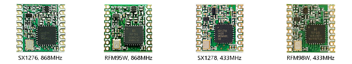
Semtech SX127x LoRa transceivers and HopeRF RFM9x LoRa transceivers are identical. They come in different variants, depending on the targeted frequency band (433, 868 and 915 MHz). Which frequencies are used depends on the geographic region and local ISM band regulations. (HopeRF module numbers usually end with W which stands for ‘international version’.)
The ESP32 and the LoRa transceivers come in several forms:
- On modules.
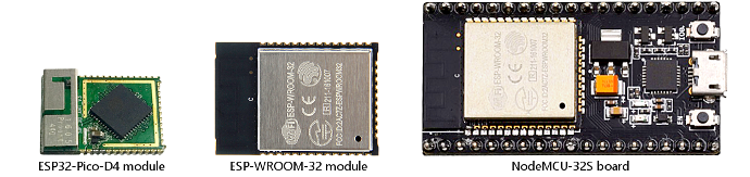
Modules contain additional components required for making the chips work. The modules use 1.27mm or 2mm pin spacing. For use with breadboards and prototyping PCB with 2.54mm spacing adapters are required. Examples: ESP-WROOM-32 ESP32 module, SX1276 and RFM95 LoRa modules. - On development boards.
Development boards (often) convert to 2.54mm spacing and add additional functionality like power converter, buttons and LEDs. Development boards use either standard modules or separate components. Examples: ESP32 Dev board, Lolin32 and NodeMCU-32S. A pure adapter is the HopeRF RFM95 adapter. - On custom boards which combine ESP32 with a LoRa transceiver.
Custom boards can use standard modules, separate components or a combination of both.
Examples: Heltec Wifi LoRa 32 and TTGO LoRa32.
IDE’s and Development Frameworks
There are two frameworks that can be used for ESP32 development: ESP-IDF and Arduino. ESP-IDF is a dedicated for the ESP32 and best supports all ESP32 features. Arduino is very popular because it is cross-platform, has wide community support and has many libraries available. ESP32 Arduino core which is used for Arduino development is based on the ESP-IDF.
PlatformIO will install support for ESP32 automatically. For the Arduino IDE this will have to be done manually: See Installing ESP32 support for Arduino IDE.
LoRaWAN library
In addition to the hardware, software is needed for implementing the LoRaWAN protocol. The SX127x LoRa tranceiver provides LoRa radio modulation but it does not implement the LoRaWAN protocol. The protocol has to be implemented in software that needs to run on the ESP32.
MCCI LMIC is the preferred LoRaWAN library for Arduino development. It is the most mature, most complete LMIC library for Arduino and it is actively maintained. Do read its README.md first and be aware that the library is default configured to use the us915 frequency plan so most people will need to change its configuration. It’s predecessor library Classic LMIC is no longer maintained.
Examples - Get the basics working first
See [update] below.
Always get the basic examples working first because this will make it much easier to troubleshoot LoRaWAN issues and beginner mistakes.
Only after the essential basics are working should you start adding more features (e.g. add support for reading and uploading sensor data, send output to OLED display etc.).
The library includes two essential basic examples: ttn-otaa.ino and ttn-abp.ino. These are the ‘Hello World’ type examples for The Things Network. ttn-otaa.ino uses OTAA activation (preferred) and ttn-abp.ino uses ABP activation.
For TTN V2 it was advised to:
Get the ttn-abp.ino example working first because V2 does not require downlink support for ABP (V3 does), the example uses uplink messages only and is therefore simpler to test . If that works continue with the ttn-otaa.ino example. Latter also uses uplink messages only but OTAA requires downlinks to work otherwise the join will fail.
For V3 (The Things Stack V3) things have changed:
In V3 registering an ABP node is more complex and requires more details to be specified for an ABP device than for an OTAA device and requires more LoRaWAN knowledge. Therefore it will be easier to try ttn-otaa.ino first and if that works just skip ttn-abp.ino. Latter can still be useful for helping detect downlink issues but registering an ABP device is more complex and for proper LoRaWAN operation V3 actually also requires downlink support for ABP devices.
Use of OTAA is strongly preferred. OTAA and ABP require different settings. See TTN Console and remarks in the examples for more information.
[update]
LMIC-node
LMIC-node is a very complete cross-platform example application. It uses the LMIC library and supports most boards described in this topic out of the box. LMIC-node is well documented, provides useful status information (to serial monitor and onboard display) and does not require programming or changing source code to get your node up and running.
It is more advanced than the above described ttn-otaa.ino and ttn-abp.ino examples.
If LMIC-node supports your board (see REAME.md) then it is preferred and advised to use LMIC-node instead of the examples included with the LMIC library. You can find LMIC-node here:
In addition you can find pinout diagrams for most boards here:
OLED Display library
A popular library for monochrome OLED displays is: U8g2
This library is easy to use and supports primitive graphics operations and different fonts.
It is well-documented and contains several examples. It also contains U8x8 which is a subset that only supports text, 8x8 fonts and custom definable characters. U8x8 uses less memory and CPU resources.
Some popular ESP32 LoRa development boards
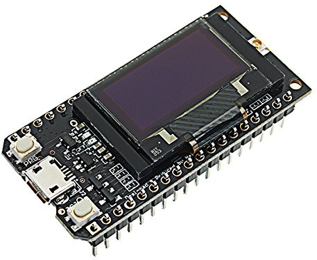
The following boards are popular for prototyping because they combine an ESP32, a LoRa tranceiver and LiPo/Li-Ion battery support with charging in one small package. The LoRa32 models also have a an 128x64 OLED display and can be used on a breadboard.
- Heltec Wifi LoRa 32
- Heltec Wireless Stick (Lite)
- Heltec Wireless Shell
- TTGO LoRa32
- TTGO T-Beam
- Pycom Lopy4
These boards come in different versions and there are separate versions for 433/470MHz and 868/915MHz.
LoRa antenna: external, connected via cable with I-PEX connector. TTGO LoRa32 V2.1.x versions use an SMA connector so the antenna can be directly mounted to the board.
Battery connector: 2-pin Molex PicoBlade (1.25mm spacing). Compatible connectors: ‘JST 1.25mm’ sold on AliExpress and eBay (sold as JST-PH 1.25mm but it is not PH because PH uses 2.0mm spacing).
Take care with battery cables (that were not included with the board): check first if the colors of the cable match the polarity of the battery connector on the board (the colors may fool you). Connecting the battery reversed can destroy the board.
Important: Over time new versions of existing boards have been and will be released. This usually includes changes in pin layout, changes in functionality and remapping of GPIOs for different functions.
Often, especially with older boards, it is not be possible to easily determine the product version on the outside because a product/version label is missing on the PCB.
Always check the type and version of your board and compare it with what is currently documented.
Using incorrect settings for your board will not make it work properly and using an incorrect pin layout (because layout changes were introduced in a new version, usually without any warning) could possibly damage your board and/or connected hardware.
Disclaimer: Information in this rticle is composed with best efforts and comes from different sources. Documentation is sometimes unavailable or not always reliable (TTGO) and not all boards were available for testing.
If you have any additional information about these boards then please share below.
If you find any errors then please leave feedback so this can be fixed.
LoRa Development Boards
All below ESP32 LoRa development boards support LoRa, Wi-Fi and Bluetooth and all are breadboard friendly.
Heltec Boards
The ‘LoRa’ boards have a white PCB and the ‘Wireless’ boards have a black PCB. These boards come in different versions:
-
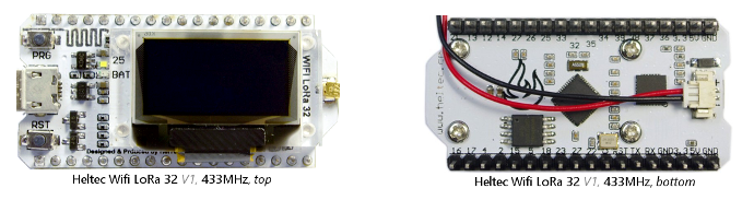
Heltec Wifi LoRa 32 V1:
Has on-board PCB WiFi/Bluetooth antenna. Appears to be available for 433MHz only. -
Heltec Wifi LoRa 32 V1.2:
Has small on-board helical antenna (has a PCB antenna on the bottom but that is not connected). (Note that V1.2 is not an official Heltec version number). -
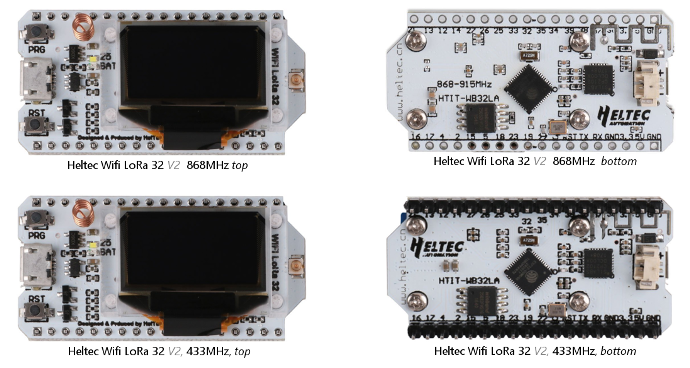
Heltec Wifi LoRa 32 V2:
Similar to V1.2 but has some improvements and DIO pin mappings have changed.
V2 can be recognized by a “V2” label near the IPEX antenna connector. -
Heltec Wireless Stick:
One of the newer Heltec ESP32 boards that is better optimized for low power batteryusage. It has a tiny 0.49" OLED display, an external LoRa antenna connected via U.FL antenna connector and on-board Wifi antenne. Advertised deep sleep current is 800 uA. More information is currently not provided in this topic (see Heltec site for more information). -
Heltec Wireless Stick Lite:
One of the newer Heltec ESP32 boards that is better optimized for low power battery usage. It has no display, an external LoRa antenna connected via U.FL antenna connector and on-board Wifi antenne. Advertised deep sleep current is 30 uA. More information is currently not provided in this topic (see Heltec site for more information. -
Heltec Wireless Shell:
One of the newer Heltec ESP32 boards that is better optimized for low power battery usage. It has no on-board USB to serial, no display, and no on-board antennas. The external LoRa and Wifi antennas are connected via U.FL antenna connectors. Advertised deep sleep current is 10 uA. More information is currently not provided in this topic (see Heltec site for more information.
TTGO Boards
These boards all have a black PCB and come in different versions:
-
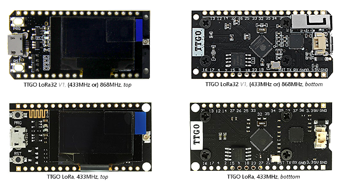
TTGO LoRa:
Has on-board PCB Wifi/Bluetooth antenna on top. Uses SX1278, 433MHz only. Also available without the display. -
TTGO LoRa32 V1.0:
Has on-board metal Wifi/Bluetooth antenna on bottom. Uses SX1276. I-Pex connector located on top. LilyGO now appears to call this board TTGO LoRa V1 (without the 32). -
TTGO LoRa32 V1.3:
A while ago (after V2.x was already released) LilyGO introduced a new version: V1.3. Compared to V1.0 it has the following improvements:
1.Product low power design
2.Optimize LORA RF circuit
3.Add battery voltage detection Pin IO35
I’m not aware if V1.3 has introduced any pin layout changes. -
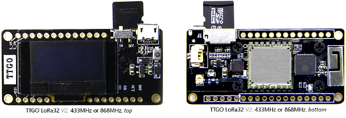
TTGO LoRa32 V2.0 (aka LoRa32 V2):
There is no version label on the PCB.
Has on-board metal Wifi/Bluetooth antenna on bottom (in a better location than V1).
Uses ESP32-Pico-D4 (with integrated flash memory) instead of ESP32, uses a (shielded) SX1276 LoRa module, I-Pex connector located on the bottom, micro-USB connector is rotated 90 degrees, in addition has a microSD card slot on the bottom and an on/off switch for the battery next to the micro-USB connector. Switches the battery only so not possible to switch the board off when connected to USB for charging the battery.
User LED is connected to GPIO25 which is useless because that is already used for the display and all LEDs are on the bottom side. DIO1 and DIO2 have a separate pins and are not wired on the PCB to a GPIO port so must be manually wired. The LoRa modules are HPD13A and HPD14A from HPDTek.
Pinout diagram: TTGO LoRa32 V2.0 Pinout v3.0.pdf -
TTGO LoRa32 V2.1.5 (aka T3 V1.5, aka LoRa32 V2.1 release 1.5):
Is labeled V1.5 on the PCB (apparently without a date).
Similar to V2.0 with changes and improvements:
Changes in pins / GPIOs, uses GPIO12 for LoRa RST.
SMA LoRa antenna connector, different battery charging chip, different switch. -
TTGO LoRa32 V2.1.6 (aka T3 V1.6, aka LoRa32 V2.1 release 1.6):
Is labeled T3 V1.6, 20180506 on the PCB.
Similar to V2.1.5 with changes and improvements:
Changes in pins / GPIOs. Uses GPIO23 for LoRa RST. Uses GPIO25 for onboard LED. Uses GPIO35 as ADC for battery voltage measurement (uses 100k/100k divider). -
TTGO T-Beam versions V0.6, V0.7, V1.0 and V1.1 (aka TTGO T22):
In addition to the above TTGO boards the T-Beam has on-board GPS, 18650 Li-ion cell battery holder and SMA antenna connector. It does not have an on-board display.
Versions V1.0 and V1.1 use a programmable AX192 power management chip. The AXP needs to be configured in code to enable power and the correct voltages to elements on the board. Without configuring the AXP many things will not work. See the TTGO T-Beam topic topic for more information.Until recently the T-Beam boards were standard fitted with a SX127x LoRa tranceiver. However, since 2020 Q4 there also exist T-Beam (V1.1) boards that come fitted with the newer SX1262 LoRa tranceiver. Both configurations are called T-Beam V1.1 so be aware what you buy when ordering a board. There is still very limted SX1262 support for the Arduino framework.
 Warning: The SX1262 is (currently) NOT supported by MCCI LMIC or Classic LMIC.
The T-Beam with SX1262 requires a different LoRaWAN library that supports the SX1262 and is not covered in this topic.
Pycom Boards
Pycom boards are designed for use with MicroPython but they can be programmed with C/C++.
For C/C++ development they are not developer friendly because:
(1) There is no on-board USB.support nor a separate serial connector for connecting a USB to Serial adapter. (2) The boards must be put manually in firmware upload mode but even a GPIO0 button is missing which makes things even less practical. Pycom sells an Expansion Board that provides on-board USB to Serial but it lacks both an auto firmware upload mode and a GPIO0 button.
-
Lopy4:
Has no onboard antennas. Both LoRa and Wifi antennas are external and connected via U.FL antenna connector. It has no display. Has on-board WS2812 RGB LED. In addition to LoRa the Lopy4 also supports Sigfox. More information is currently not provided in this topic (see Pycom site for more information.
Arduino Board Definitions
In the ESP32 Arduino Core at least the following ESP32 LoRa boards are defined:
| Board | Arduino IDE name | Arduino board ID | PlatformIO board ID |
|---|---|---|---|
| Heltec Wifi LoRa 32 | Heltec WiFi LoRa 32 |
ARDUINO_HELTEC_ WIFI_LORA_32 |
heltec_wifi_ lora_32 |
| Heltec Wifi LoRa 32 V2 | Heltec WiFi LoRa 32(V2) |
ARDUINO_HELTEC_ WIFI_LORA_32_V2 |
heltec_wifi_ lora_32_v2 |
| TTGO LoRa32 V1.x | TTGO LoRa32-OLED V1 |
ARDUINO_TTGO_ LoRa32_V1 |
ttgo-lora32-v1 |
| TTGO LoRa32 V2.x | TTGO LoRa32-OLED V1 |
ARDUINO_TTGO_ LoRa32_V1 |
ttgo-lora32-v1 |
| TTGO T-Beam V0.x | T-Beam | ARDUINO_T_Beam | ttgo-t-beam |
| TTGO T-Beam V1.x | T-Beam | ARDUINO_T_Beam | ttgo-t-beam |
| Pycom LoPy | LoPy | ARDUINO_LoPy | lopy |
| PyCom LoPy4 | LoPy4 | ARDUINO_LoPy4 | lopy4 |
For TTGO LoRa32 V2.0, V2.1.5, V2.1.6 and T-Beam V1.0, V1.1 currently no separate board definitions exist. Use the board definition that best matches your board (in name and version).
GPIO Pin Mappings
Heltec Wifi LoRa 32, TTGO LoRa, TTGO LoRa32 V1.0, TTGO LoRa32 V1.3:
ESP32          LoRa (SPI)      Display (I2C)  LED
-----------    ----------      -------------  ------------------
GPIO5  SCK     SCK
GPIO27 MOSI    MOSI
GPIO19 MISO    MISO
GPIO18 SS      NSS
GPIO14         RST
GPIO26         DIO0
GPIO33         DIO1  (see #1)
GPIO32         DIO2  (see #1)
GPIO4                          SDA
GPIO15                         SCL
GPIO16                         RST (see #2)
GPIO25                                        LED - Heltec and TTGO LoRa32 (see #3)
GPIO2                                         LED - TTGO LoRa
- Similar to DIO0, DIO1 and DIO2 are already hardwired on the board.
For some other versions off TTGO boards DIO1 and DIO2 have to be manually wired.
I assume this are already hard wired for the newer TTGO LoRa32 V1.3, but like for
TTGO LoRa32 V1.0 there is no documentation from LilyGO that documents this. - TTGO LoRa32 V1.3 uses power-up hardware reset for display (NOT a GPIO).
- TTGO LoRa32 V1.3 does not have a user programmable LED.
Heltec Wifi LoRa 32 V2:
ESP32          LoRa (SPI)      Display (I2C)  LED
-----------    ----------      -------------  ------------------
GPIO5  SCK     SCK
GPIO27 MOSI    MOSI
GPIO19 MISO    MISO
GPIO18 SS      NSS
GPIO14         RST
GPIO26         DIO0
GPIO35         DIO1
GPIO34         DIO2
GPIO4                          SDA  (use pin definition SDA_OLED not SDA)
GPIO15                         SCL  (use pin definition SCL_OLED not SCL)
GPIO16                         RST
GPIO25                                        LED
Warning!: The I2C hardware interface consists of 2 lines: SDA and SCL.
          In Arduino board definitions the names 'SDA' and 'SCL' normally
          map to the corresponding GPIO pins of the I2C interface.
          However, for the Heltec Wifi LoRa 32 V2 board 'SDA' and 'SCL'
          are incorrectly defined!: SDA is defined as 21 and SCL as 22.
          But on the Heltec Wifi LoRa 32 V2 board GPIO21 is used for switching
          VExt output instead and is not used for SDA.
          The V2 board uses GPIO4 for SDA and GPIO15 for SCL instead.

          When using the Wire (I2C) interface in Arduino, it by default will use
          pin definitions 'SDA' and 'SCL' which for Wifi LoRa 32 V2 are
          incorrect! *Any any sketch and any library* that initializes the
          Wire interface by calling Wire.begin() without parameters
          (which is common) will use the wrong pins for SDA and SCL!

          As workaround you must explicitly call Wire.begin(SDA_OLED, SCL_OLED)
          AT THE START of setup() BEFORE initializing any libraries.
          This will configure the wire interface to use
          the correct GPIO pins for SDA (4) and SCL (15).
          If you omit this then the I2C (Wire) interface and its connected
          peripherals will not work and strange things may happen to VExt.
TTGO LoRa32 V2.0:
ESP32          LoRa (SPI)      Display (I2C)  LED
-----------    ----------      -------------  ------------------
GPIO5  SCK     SCK
GPIO27 MOSI    MOSI
GPIO19 MISO    MISO
GPIO18 SS      NSS
-              RST
GPIO26         DIO0
GPIO33         DIO1 (see #1)
GPIO32         DIO2 (see #2)
GPIO21 SDA                     SDA
GPIO22 SCL                     SCL
GPIO22                                        LED useless (see #3)
- Required. Not wired on PCB, must be manually wired.
- Optional (needed for FSK only). Not wired on PCB.
- GPIO22 is already used for SCL therefore LED cannot be used without conflicting with I2C and display.
TTGO LoRa32 V2.1.5:
ESP32          LoRa (SPI)      Display (I2C)  LED
-----------    ----------      -------------  ------------------
GPIO5  SCK     SCK
GPIO27 MOSI    MOSI
GPIO19 MISO    MISO
GPIO18 SS      NSS
GPIO12         RST
GPIO26         DIO0
GPIO33         DIO1 (see #1)
GPIO32         DIO2 (see #2)
GPIO21 SDA                     SDA
GPIO22 SCL                     SCL
GPIO23                                        LED
- Required. Unknown if this already wired on PCB or must be manually wired.
- Optional (needed for FSK only). Unknown if this already wired on PCB.
TTGO LoRa32 V2.1.6:
ESP32          LoRa (SPI)      Display (I2C)  LED
-----------    ----------      -------------  ------------------
GPIO5  SCK     SCK
GPIO27 MOSI    MOSI
GPIO19 MISO    MISO
GPIO18 SS      NSS
GPIO23         RST
GPIO26         DIO0
GPIO33         DIO1
GPIO32         DIO2
GPIO21 SDA                     SDA
GPIO22 SCL                     SCL
GPIO25                                        LED
TTGO T-Beam V0.x, V1.0 and V1.1:
ESP32          LoRa (SPI)      I2C            LED
-----------    ----------      -------------  ------------------
GPIO5  SCK     SCK
GPIO27 MOSI    MOSI
GPIO19 MISO    MISO
GPIO18 SS      NSS
GPIO23         RST
GPIO26         DIO0
GPIO33         DIO1
GPIO32         DIO2
GPIO21 SDA                     SDA
GPIO22 SCL                     SCL
GPIO14                                        LED (see #1)
- Not sure / not checked if true for T-Beam V1.1
Software Configuration
Configure LMIC pin mappings for the LoRa tranceiver:
// For Heltec Wifi LoRa 32, TTGO LoRa, TTGO LoRa32 V1.0 and
// TTGO LoRa32 V1.3:
const lmic_pinmap lmic_pins = {
    .nss = 18,
    .rxtx = LMIC_UNUSED_PIN,
    .rst = 14,
    .dio = {/*dio0*/ 26, /*dio1*/ 33, /*dio2*/ 32}
};
// For Heltec Wifi LoRa 32 V2:
const lmic_pinmap lmic_pins = {
    .nss = 18,
    .rxtx = LMIC_UNUSED_PIN,
    .rst = 14,
    .dio = {/*dio0*/ 26, /*dio1*/ 35, /*dio2*/ 34}
};
// For TTGO LoRa32 V2.0:
// Do not forget to manually wire DIO1 to GPIO33.

const lmic_pinmap lmic_pins = {
    .nss = 18,
    .rxtx = LMIC_UNUSED_PIN,
    .rst = LMIC_UNUSED_PIN,
    .dio = {/*dio0*/ 26, /*dio1*/ 33, /*dio2*/ LMIC_UNUSED_PIN}
}
// For TTGO LoRa32 V2.1.5:
// If not already wired on PCB:
// do not forget to manually wire DIO1 to GPIO33.

const lmic_pinmap lmic_pins = {
    .nss = 18,
    .rxtx = LMIC_UNUSED_PIN,
    .rst = 12,
    // If DIO2 is not wired use:
    .dio = {/*dio0*/ 26, /*dio1*/ 33, /*dio2*/ LMIC_UNUSED_PIN}
    // If DIO2 is wired use:
    // .dio = {/*dio0*/ 26, /*dio1*/ 33, /*dio2*/ 32}
}
// For TTGO LoRa32 V2.1.6 and TTGO T-Beam versions V0.x, V1.0 and V1.1:

const lmic_pinmap lmic_pins = {
    .nss = 18,
    .rxtx = LMIC_UNUSED_PIN,
    .rst = 23,
    .dio = {/*dio0*/ 26, /*dio1*/ 33, /*dio2*/ 32}
}
Configure the U8g2 library for the OLED display:
//U8x8 configuration
//See U8g2/U8x8 documentation for available display functions

#include <U8x8lib.h>

//For Heltec Wifi LoRa 32, TTGO LoRa and TTGO LoRa32 V1 use:
U8X8_SSD1306_128X64_NONAME_HW_I2C display(/*rst*/ 16, /*scl*/ 15, /*sda*/ 4);

//For TTGO LoRa32 V2.x use:
U8X8_SSD1306_128X64_NONAME_HW_I2C display(/*rst*/ U8X8_PIN_NONE);

//Add to setup():
Wire.begin(SDA_OLED, SCL_OLED);  // This line ONLY FOR Heltec Wifi LoRa 32 V2!!!
display.begin();
display.setFont(u8x8_font_victoriamedium8_r);
Example hardware
Below pictures are provided as examples to give an impression. Below pictures do not include all the latest new versions and new models. Below pictures all have the same size ratio.
ESP32 modules / boards
LoRa Tranceiver modules
Heltec boards
Errata: Note that the V2 version labels shown in the captions of below Heltec boards are incorrect and should be read as V1.2 instead.
Heltec did actually not use any official version number up until they came with a new version of the board that has explicitly been labeled V2 (near the IPEX antenna connector).
The official V2 is not shown in the images below but looks similar to V1.2 (except that some chips are arranged differently on the PCB). The official V2 uses different DIO pin mappings.
TTGO boards