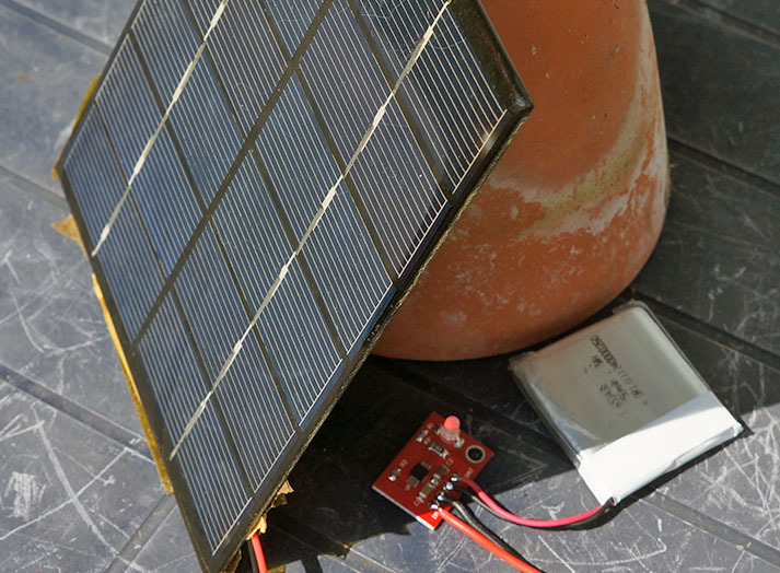
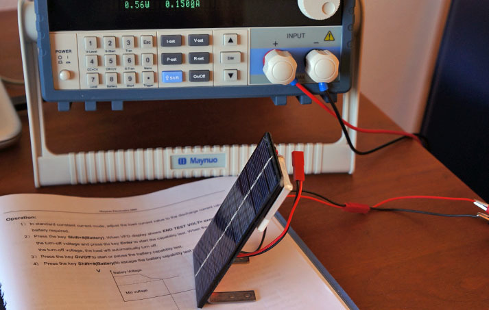
ah there’s the sun, time to test this one on an empty 750 mA LiPo
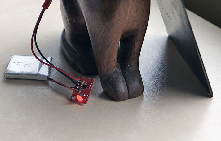
indoor behind glass clouded day test 
ah there’s the sun, time to test this one on an empty 750 mA LiPo
indoor behind glass clouded day test
@BoRRoZ : Huge solar panels, what kind of power requirements do you have ?
you think 6V - 2W - 330 mA = huge ?
I put this setup yesterday afternoon in the sun - it filled the LiPo during that time with 360 mA
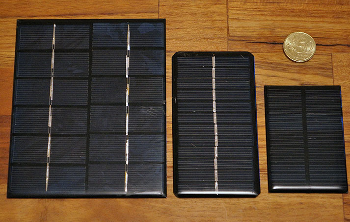
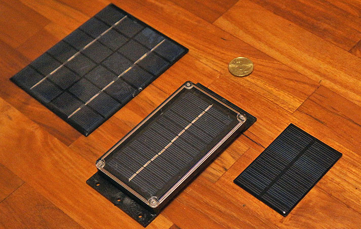
but I have some smaller panels coming soon
0.6W 6V 80 x 55mm
1W 6V 110 x 60mm
2W 6V 330mA 136 x 110mm
A small node with a very small solar panel looks nice, could work very well in certain countries with many sun hours, but during winters and a clouded weeks you’ll need a bigger battery and a bigger solar panel to charge it faster.
All depending on how much ‘juice’ your node&sensors wants to consume of course.
It depends of your power requirement. An RFM95 transmitting data + ATmega328 is about 35 mA. About 1.5 second is required to transmit 10 bytes in SF12, 0.5 sec for the application. Data are send every 5 minutes, which gives 352/360012=0,233 mA/hour, I add 4 uA for standby power consumption.
With 1000 mA, it can last 175 days. If the device is connected to TTN with fair policy restriction it will be a lot more. (times 12 ?)
Of course this simple figure does not take into account self-discharge nor temperature factor but lot of modern uC are less hungry than the ATmega328, so I was just curious about your application ![]()
Also, Charles spoke about ESP8266 which I don’t know very well the power consumption…
The figures I used are from my sensor connected to solar panel, even if I still need to measure all of them. Also, I tinker around the solar panel yesterday and it seems that my boost converter is far from efficient ! I hope to have some time to characterize it after my vacations but connecting the solar panel directly to the TP4056 works where using the boost did not. By the way, I can’t wait to receive my CN3065 to improve the efficiency ![]()
they seemed to work very well ![]()
@BoRRoZ, I think I missed one important information how consumption can be can be 35mA ? RFM95 datasheet says (several so not sure what the real value)
One page => 120mA
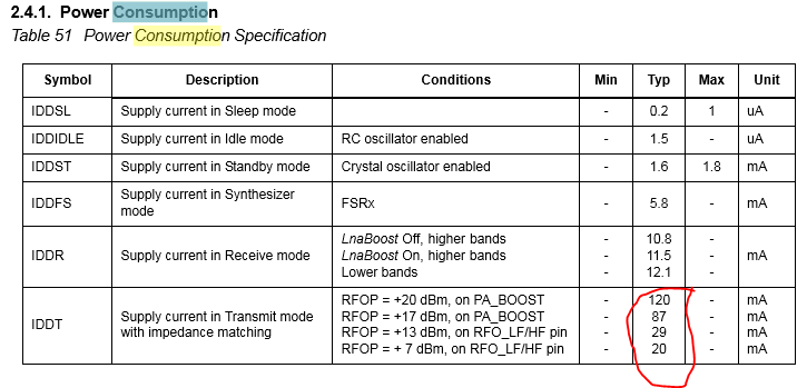
Another One => 90mA
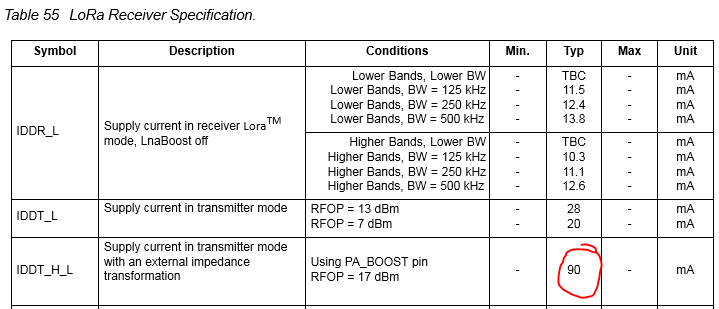
If I understand what you’re writing, does this mean Lora never use PA_BOOST?
I use LTC3105 for solar controller (because need small device and panel ~ 40x15 mm)
Real consumption for RF part ~ 80mA and small battery + supercap provide 2-3 seconds to transmitte. Device size ~ 35x20 mm with sensors, gps.
@charles : True I made a mistake, but we should transmit at 14 dB max in EU, so around 30mA I assume. I will record it after my holydays, I only checked standby current to be sure that the module enters in sleep mode.
@x893 : nice ! Did you post some data somewhere about them ? Which duty cycle ? I wanted to try a supercap only…
@Oliv
oh yes 14dB max, that’s the trick, and so why it’s limited to ~30ma which in fact is perfect for me, got a node that can’t go over 90mA
thanks for sharing
received the board and a little disapointement is, that the LiPo connector is 0.1" which is not standard for all my batteries I have.
That should be corrected or at leased two solder holes added.
I would also like 2 solder points/holes close to the micro-usb as input from the solar panel
otherwise the board is of high quality!
still searching for the optimal combination for a small sensornode , and its a sunny day yeah !!
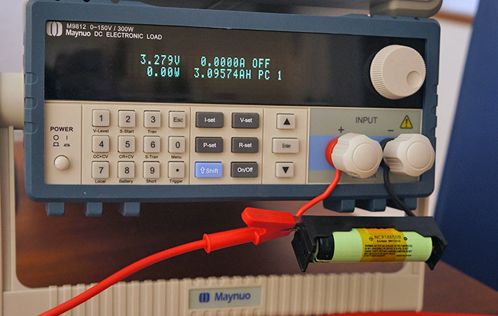
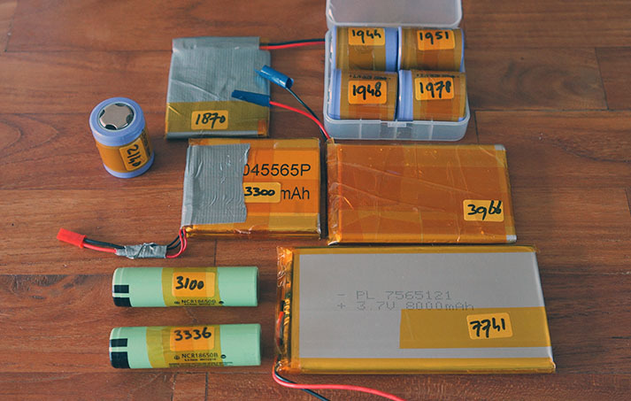
wow … an 18650 with a real capacity of more then 3100 mAh
(discharged for > 3 hours @ 1 Ah to 3V)
one of the best i’ve seen : panasonic NCR 18650B (used in el. cigarettes)
Guys,
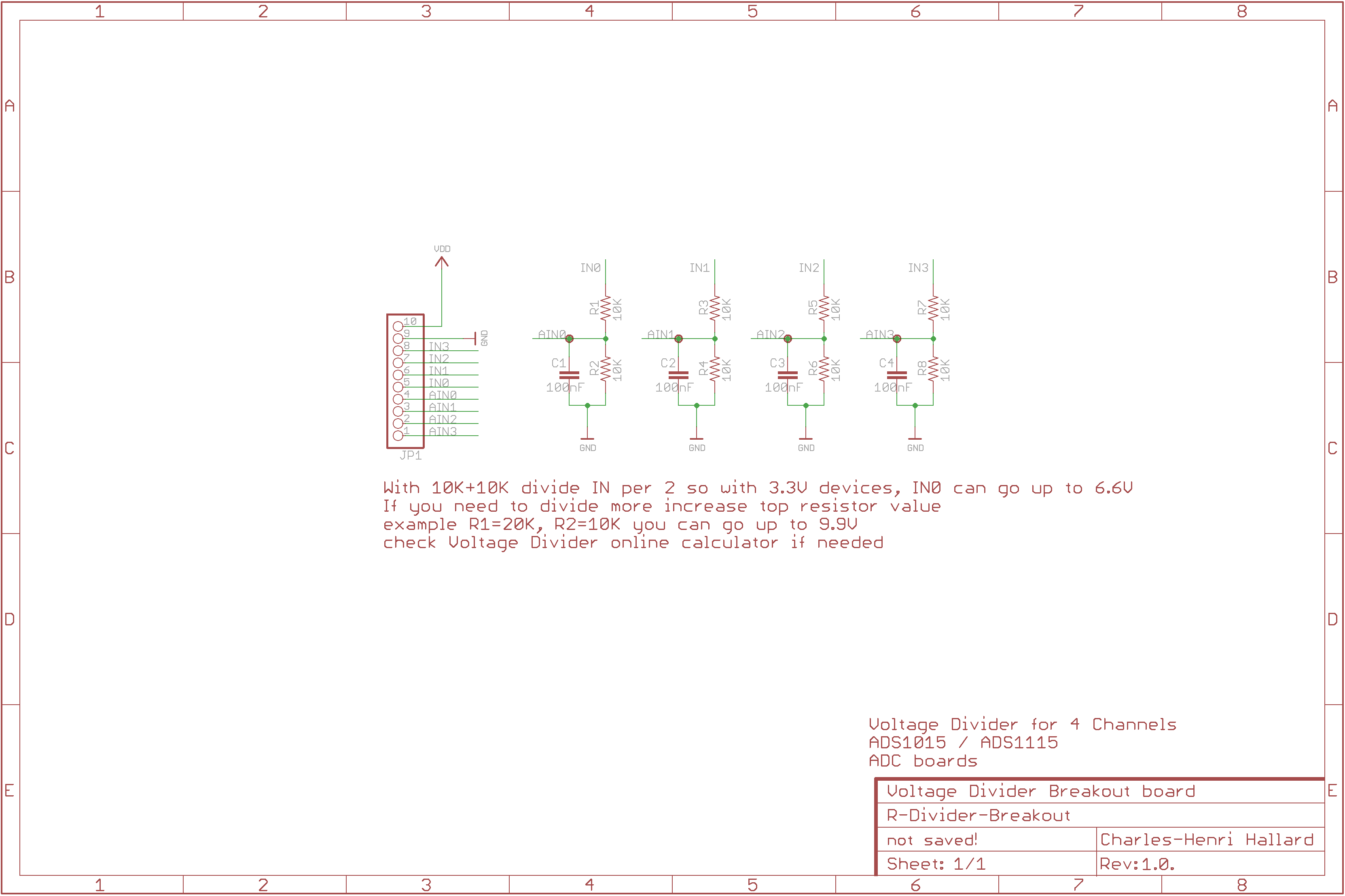
I mounted R-Divider breakout board, time to get some code working, but ready to measure from any 3.3V CPU with I2C and no descent Analog input, ohh, did I say ESP8266 ?
Here are picture, as you can see, seems PCBs.io silk is much better now, really close to OSHPark
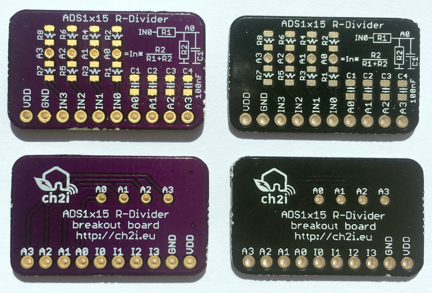
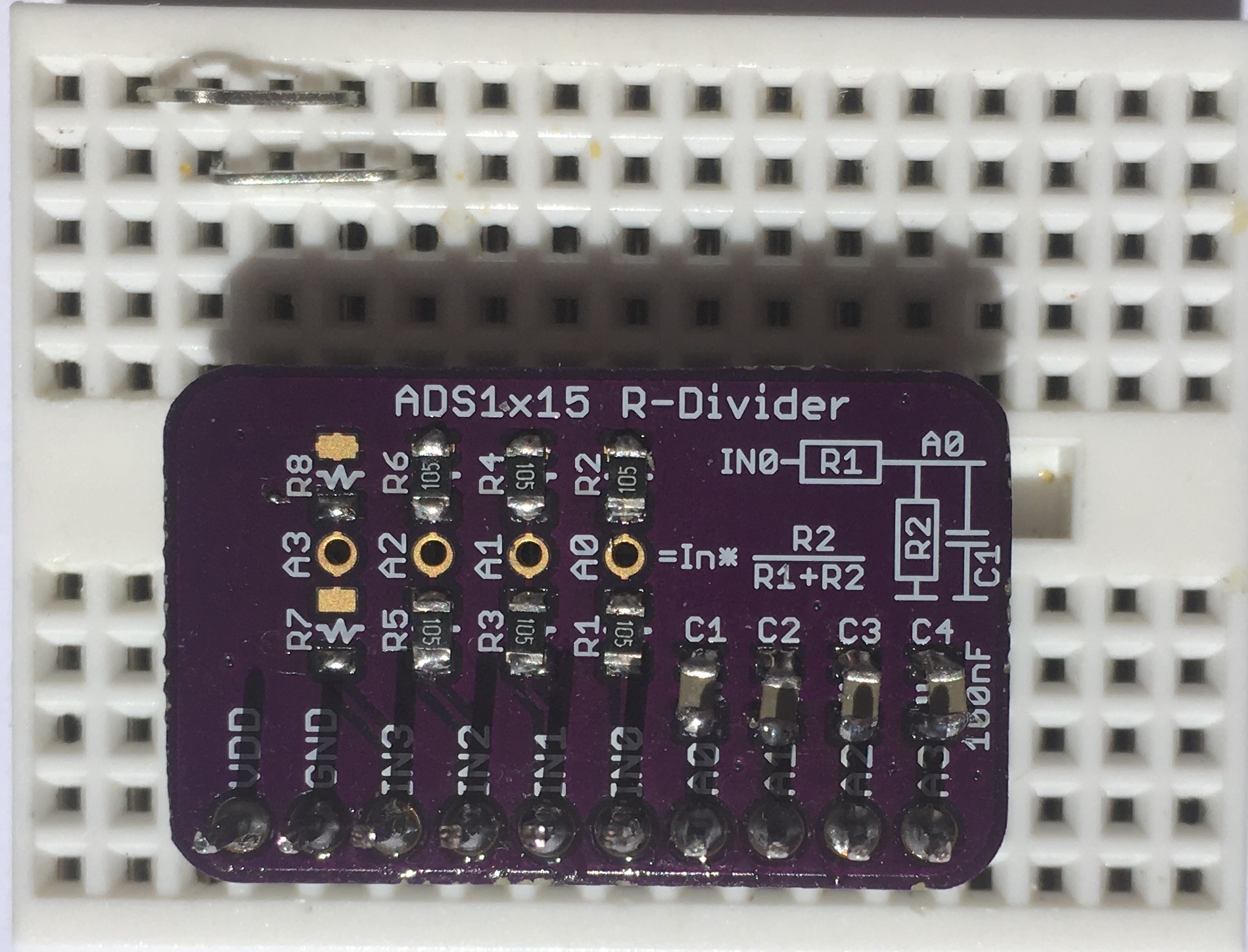
Assembled
I’ve just put 1% 1M+1M Resistors and 100nF filtering, so we divide input voltage by 2 (so up to 6.6V input)
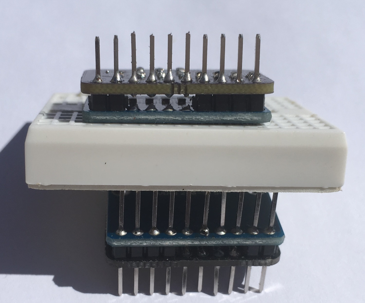
Assembled and stacked with ADS1115
I was looking at the schematic but couldn’t find the chip you use 
@BoRRoZ
It’s just a R-Divider (if you already have Analog input on device) and if not (like ESP8266) you can stack it with ADS1115 board (I2C 4 ADC inputs) like below. You can see github readme for more information
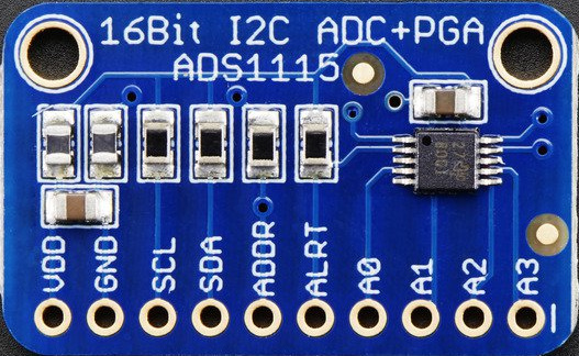
You can find this ADS1115 board (new version smaller) on ebay for less than $3
ah ok tnx
and you know… not all LiPo’s are equal - never believe what’s printed on them
Hey, yeah I know that, how do you find the real value, you count time to fully charged to discharge at specific AMP ?
yes , I have 2 possibillities, the Maynuo M9812 electronic load and the Turnigy Accucell 6
The Maynuo have a special battery testfunction and can, when connected to PC spit out information/graphs
You set the end voltage (normal between 2.75 and 3.2 V depends on the buildin protection circuit/datasheet)
and you set the discharge current (between 0.2 and 1 C)
then push start and go do the dishes/do some shopping and when reached the end voltage it stops discharging and give you the mAh.
what I really need is a logging power tool… like Ladyada
have been busy finding a diy solution
just curious, did you ever measure the cheap ‘action’ 2000mah AA powerbase batteries?
no, have been testing chinese Ultrafires … that’s really crap