Arduino nano and RFM95 basic test - EV_JOIN_TXCOMPLETE: no JoinAccept

Hello,

I’ve searched this forum for related keywords “EV_JOIN_TXCOMPLETE: no JoinAccept” - but I didn’t identified any solution. Maybe someone can help me to understand where is the problem.

I have followed 2 examples to test. This and this.

All I see in arduino console is:
Starting
Packet queued
1818: EV_JOINING
479048: EV_TXSTART
874704: EV_JOIN_TXCOMPLETE: no JoinAccept

And on the TTN console my device is never seen.

I have tried different settings on TTN side and arduino side, OTAA then ABP methods, - nothing helps. DEVEUI, APPEUI, APPKEY are in correct order (lsb,lsb,msb). I have tried to put wrong DEVEUI, APPEUI and APPKEy to see if the error message in the console will be different, but I see the same message EV_JOIN_TXCOMPLETE: no JoinAccept

I have tested communication between 2 lora nodes RFM95 to check if the radios are OK and it works fine. The problem is only with lorawan LMIC. I have tried different versions of LMIC library - not helped.

I thought maybe I’m too far from the gateway. I have found on the map 2 active gateways. I was very close to these gateways but my device is still never seen.

I cannot see what’s happening in the network. Is my paket really sent? It reaches the gateway? Why no join?
The packet seems to be sent but never reaches TTN even if I’m very close to the active gateways. The frequency is right for Europe 868Mhz.

What other things I need to check? If it works with arduino pro mini, like seen in examples above, it should work with arduino nano too, I think.

It may work, but as the RFM95’s run on 3.3V and the Nano runs on 5V, mostly people get away with it, sometimes it doesn’t.

I’d use this: GitHub - descartes/Arduino-LMIC-example: Known good Arduino ATmega328 + LoRa chip LoRaWAN node but swap the LMIC over to GitHub - matthijskooijman/arduino-lmic: ⚠ This library is deprecated, see the README for alternatives. and you can now use the latest Arduino IDE. Start out simple with the LMIC ABP example.

1 Like

I’ve seen here people talking about 5V and 3.3V incompatible modules, but I never thought this is my case because it’s my first test and because on the arduino nano board I see a pin named 3V3. I decided to test now if it’s really 3.3V output. My multimeter shows 4.13V on 3.3V pin on the arduino nano. Let’s say it’s a problem. But why then 2 arduino nano + RFM95 nodes can communicate without problem with lora sender/receiver, but cannot work with lorawan LMIC? It’s the same voltage.

I followed your idea about arduino-lmic library. Installed, swapped my app to ABP on TTN, edited LMIC ABP example according to the keys, and the pin numbers. Now I see these repeating messages in arduino console:

Packet queued
131153: EV_TXCOMPLETE (includes waiting for RX windows)

My device is still never seen on TTN.
If the problem is between arduino nano and RFM95 (5V-3.3V), As an idea, I have an adafruit trinket m0 for testing, it’s a 3.3V board (voltage is really 3.3V after measurement) and it has SPI, but I can’t find an example and I’m not sure if it will work.

I also could try to drop down 4.13V to 3.3V on arduino nano, if this is the only one solution.

That will be required to prevent damage to the modules.

You have a join issue. There is plenty of information on how to debug and possible causes on the forum. Not finding it depends on search term, not on the information not being there,

If you are sure there are operational full gateways in radio range you need to check the EUIs and key. Make sure these are in the right byte order.
For ABP, make sure you use the right byte order here as well.

Still searching…

Checked. Right bytes order or wrong bytes order makes no difference. See my first post.

For ABP I used NwkSKey and AppSKey in hex big endian order (msb) and DevAddr in hex.

I think maybe a channel issue? Frequency is 868 but how the gateway and my device are according the right channel?
I’ve tried with and without all 8 channel sections code (you can find it here) and no changes.
As well as different values for LMIC_setClockError(MAX_CLOCK_ERROR * 1 / 100); - not helps.

You don’t get to choose a set frequency, they operate across the 8 channels at random with the gateway listening to all 8 channels at once. You should not need to do anything special with the default code beyond making sure you are using the right setup for your region.

As per above test using ABP as this does not require a downlink handshake, once you have ABP working you can feel confident the basics are working and switch back to OTAA - under OTAA you should be seeing a join requesting in your app within the TTN console - once you have this the next question is why your device is not receiving the join accept downlink

1 Like

OK, thanks for information. I’ll keep in mind.

debug in progress, ABP not working

Another hint found but is not this case because in my app console the frame counter is allways 0, no need to reset it.

The frame counter being zero is often the exact cause for frame counter issues. So, you’re seeing data in TTN Console? On the gateway’s Traffic page, or in the application/device’s Data page? If only in the gateway, then it sounds like a frame counter issue for sure. If you’re seeing it in the Data page, then why do you feel ABP is not working?

(If you’re only seeing it in the device’s serial output, then still frame counter security may be biting you.)

No data.

I don’t have my own gateway. I use for test public gateways arround me.

I did a frame counter reset (even if it’s zero frames) and nothing happens.

That is some Nano out of spec. The presence of a 3.3V output (that’s actually 4.13V) isn’t relevant. The problem is that the IO on the Nano runs at 5V and the IO on the RFM95 is designed for 3.3V. As I said, it often works but sometimes doesn’t. A node to node test isn’t the same as getting the more timing sensitive LoRaWAN protocol going.

Sorry to say, but the next steps usually involve having access to a gateway to see if it is hearing your device in a format that it can cope with, even if it can’t validate it. There is the possibility that the gateways close to hand aren’t online or have their own issues.

2 Likes

To exclude the frame counter issue, I have created a new TTN application and a new device and edited my code with new sessions keys. Still no data, so it’s not frame counter issue.

Thanks for explanation.

Unfortunately, I will not buy my own gateway just for testing because of price.
I’m in Paris. Here I can find a lot of alive public gateways around me. I can take with me my test radio and walk around some gateways, it should catch my packets in this area.

So, now we know that you are somewhere where we can reasonably expect you to have active gateways, that helps.

Can you post a picture of your device so we can see the connections, just in case something isn’t quite what we expect, like your location!

Wiring

This is a temporary wiring. If at least 1 packet will be sent successfuly, I will assembly all properly.

RFM95 LoRa transceiver module Arduino Pin RFM95 LoRa transceiver module Arduino Pin
ANT GND
GND GND DIO5
DIO3 RESET 5
DIO4 NSS 6
3.3V 3.3V SCK 13
DIO0 3 MOSI 11
DIO1 4 MISO 12
DIO2 GND

Connections appear OK apart from the use of the 3.3V output - the IO is going to be 5V for high, so I’ll need another coffee to figure out what levels the RFM thinks it is getting. As you are giving it 5V IO, you may as well power it with 5V.

Can you show us all of your ABP sketch so we can check out the corresponding details - feel free to blank out / remove your keys & EUI’s.

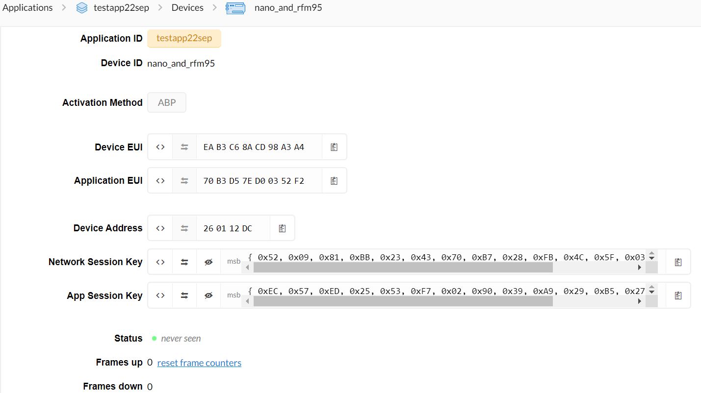
The ABP sketch from example. I edited only keys, devaddr and pins. It’s for testing, I’ll remove the app after testing. Here you can see the exact bytes order.

ttn testapp screenshot

/*******************************************************************************
   Copyright (c) 2015 Thomas Telkamp and Matthijs Kooijman

   Permission is hereby granted, free of charge, to anyone
   obtaining a copy of this document and accompanying files,
   to do whatever they want with them without any restriction,
   including, but not limited to, copying, modification and redistribution.
   NO WARRANTY OF ANY KIND IS PROVIDED.

   This example sends a valid LoRaWAN packet with payload "Hello,
   world!", using frequency and encryption settings matching those of
   the The Things Network.

   This uses ABP (Activation-by-personalisation), where a DevAddr and
   Session keys are preconfigured (unlike OTAA, where a DevEUI and
   application key is configured, while the DevAddr and session keys are
   assigned/generated in the over-the-air-activation procedure).

   Note: LoRaWAN per sub-band duty-cycle limitation is enforced (1% in
   g1, 0.1% in g2), but not the TTN fair usage policy (which is probably
   violated by this sketch when left running for longer)!

   To use this sketch, first register your application and device with
   the things network, to set or generate a DevAddr, NwkSKey and
   AppSKey. Each device should have their own unique values for these
   fields.

   Do not forget to define the radio type correctly in config.h.

 *******************************************************************************/

#include <lmic.h>
#include <hal/hal.h>
#include <SPI.h>

// LoRaWAN NwkSKey, network session key
// This is the default Semtech key, which is used by the early prototype TTN
// network.
static const PROGMEM u1_t NWKSKEY[16] = { 0x52, 0x09, 0x81, 0xBB, 0x23, 0x43, 0x70, 0xB7, 0x28, 0xFB, 0x4C, 0x5F, 0x03, 0x16, 0x5A, 0x9E };

// LoRaWAN AppSKey, application session key
// This is the default Semtech key, which is used by the early prototype TTN
// network.
static const u1_t PROGMEM APPSKEY[16] = { 0xEC, 0x57, 0xED, 0x25, 0x53, 0xF7, 0x02, 0x90, 0x39, 0xA9, 0x29, 0xB5, 0x27, 0x18, 0x3D, 0x9E };

// LoRaWAN end-device address (DevAddr)
static const u4_t DEVADDR = 0x260112DC ; // <-- Change this address for every node!

// These callbacks are only used in over-the-air activation, so they are
// left empty here (we cannot leave them out completely unless
// DISABLE_JOIN is set in config.h, otherwise the linker will complain).
void os_getArtEui (u1_t* buf) { }
void os_getDevEui (u1_t* buf) { }
void os_getDevKey (u1_t* buf) { }

static uint8_t mydata[] = "Hello, world!";
static osjob_t sendjob;

// Schedule TX every this many seconds (might become longer due to duty
// cycle limitations).
const unsigned TX_INTERVAL = 60;
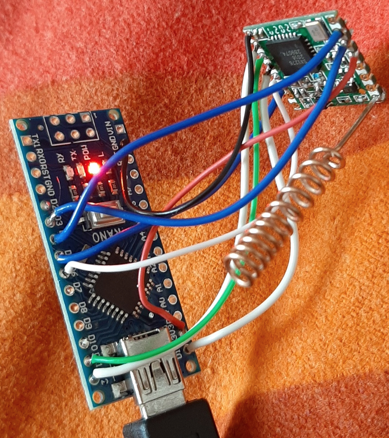
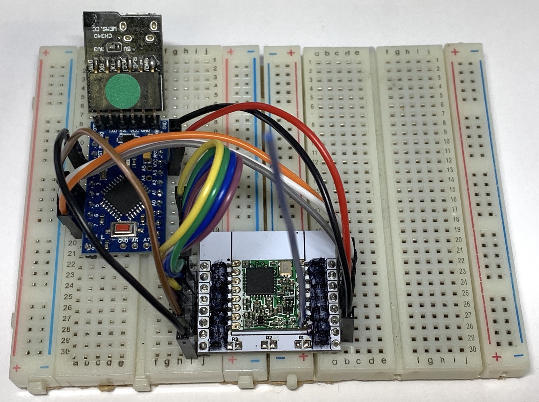
// Pin mapping
const lmic_pinmap lmic_pins = {
  .nss = 6,
  .rxtx = LMIC_UNUSED_PIN,
  .rst = 5,
  .dio = {3, 4, LMIC_UNUSED_PIN},
};

void onEvent (ev_t ev) {
  Serial.print(os_getTime());
  Serial.print(": ");
  switch (ev) {
    case EV_SCAN_TIMEOUT:
      Serial.println(F("EV_SCAN_TIMEOUT"));
      break;
    case EV_BEACON_FOUND:
      Serial.println(F("EV_BEACON_FOUND"));
      break;
    case EV_BEACON_MISSED:
      Serial.println(F("EV_BEACON_MISSED"));
      break;
    case EV_BEACON_TRACKED:
      Serial.println(F("EV_BEACON_TRACKED"));
      break;
    case EV_JOINING:
      Serial.println(F("EV_JOINING"));
      break;
    case EV_JOINED:
      Serial.println(F("EV_JOINED"));
      break;
    case EV_RFU1:
      Serial.println(F("EV_RFU1"));
      break;
    case EV_JOIN_FAILED:
      Serial.println(F("EV_JOIN_FAILED"));
      break;
    case EV_REJOIN_FAILED:
      Serial.println(F("EV_REJOIN_FAILED"));
      break;
    case EV_TXCOMPLETE:
      Serial.println(F("EV_TXCOMPLETE (includes waiting for RX windows)"));
      if (LMIC.txrxFlags & TXRX_ACK)
        Serial.println(F("Received ack"));
      if (LMIC.dataLen) {
        Serial.println(F("Received "));
        Serial.println(LMIC.dataLen);
        Serial.println(F(" bytes of payload"));
      }
      // Schedule next transmission
      os_setTimedCallback(&sendjob, os_getTime() + sec2osticks(TX_INTERVAL), do_send);
      break;
    case EV_LOST_TSYNC:
      Serial.println(F("EV_LOST_TSYNC"));
      break;
    case EV_RESET:
      Serial.println(F("EV_RESET"));
      break;
    case EV_RXCOMPLETE:
      // data received in ping slot
      Serial.println(F("EV_RXCOMPLETE"));
      break;
    case EV_LINK_DEAD:
      Serial.println(F("EV_LINK_DEAD"));
      break;
    case EV_LINK_ALIVE:
      Serial.println(F("EV_LINK_ALIVE"));
      break;
    default:
      Serial.println(F("Unknown event"));
      break;
  }
}

void do_send(osjob_t* j) {
  // Check if there is not a current TX/RX job running
  if (LMIC.opmode & OP_TXRXPEND) {
    Serial.println(F("OP_TXRXPEND, not sending"));
  } else {
    // Prepare upstream data transmission at the next possible time.
    LMIC_setTxData2(1, mydata, sizeof(mydata) - 1, 0);
    Serial.println(F("Packet queued"));
  }
  // Next TX is scheduled after TX_COMPLETE event.
}

void setup() {
  Serial.begin(115200);
  Serial.println(F("Starting"));

#ifdef VCC_ENABLE
  // For Pinoccio Scout boards
  pinMode(VCC_ENABLE, OUTPUT);
  digitalWrite(VCC_ENABLE, HIGH);
  delay(1000);
#endif

  // LMIC init
  os_init();
  // Reset the MAC state. Session and pending data transfers will be discarded.
  LMIC_reset();

  // Set static session parameters. Instead of dynamically establishing a session
  // by joining the network, precomputed session parameters are be provided.
#ifdef PROGMEM
  // On AVR, these values are stored in flash and only copied to RAM
  // once. Copy them to a temporary buffer here, LMIC_setSession will
  // copy them into a buffer of its own again.
  uint8_t appskey[sizeof(APPSKEY)];
  uint8_t nwkskey[sizeof(NWKSKEY)];
  memcpy_P(appskey, APPSKEY, sizeof(APPSKEY));
  memcpy_P(nwkskey, NWKSKEY, sizeof(NWKSKEY));
  LMIC_setSession (0x1, DEVADDR, nwkskey, appskey);
#else
  // If not running an AVR with PROGMEM, just use the arrays directly
  LMIC_setSession (0x1, DEVADDR, NWKSKEY, APPSKEY);
#endif

#if defined(CFG_eu868)
  // Set up the channels used by the Things Network, which corresponds
  // to the defaults of most gateways. Without this, only three base
  // channels from the LoRaWAN specification are used, which certainly
  // works, so it is good for debugging, but can overload those
  // frequencies, so be sure to configure the full frequency range of
  // your network here (unless your network autoconfigures them).
  // Setting up channels should happen after LMIC_setSession, as that
  // configures the minimal channel set.
  // NA-US channels 0-71 are configured automatically
  LMIC_setupChannel(0, 868100000, DR_RANGE_MAP(DR_SF12, DR_SF7),  BAND_CENTI);      // g-band
  LMIC_setupChannel(1, 868300000, DR_RANGE_MAP(DR_SF12, DR_SF7B), BAND_CENTI);      // g-band
  LMIC_setupChannel(2, 868500000, DR_RANGE_MAP(DR_SF12, DR_SF7),  BAND_CENTI);      // g-band
  LMIC_setupChannel(3, 867100000, DR_RANGE_MAP(DR_SF12, DR_SF7),  BAND_CENTI);      // g-band
  LMIC_setupChannel(4, 867300000, DR_RANGE_MAP(DR_SF12, DR_SF7),  BAND_CENTI);      // g-band
  LMIC_setupChannel(5, 867500000, DR_RANGE_MAP(DR_SF12, DR_SF7),  BAND_CENTI);      // g-band
  LMIC_setupChannel(6, 867700000, DR_RANGE_MAP(DR_SF12, DR_SF7),  BAND_CENTI);      // g-band
  LMIC_setupChannel(7, 867900000, DR_RANGE_MAP(DR_SF12, DR_SF7),  BAND_CENTI);      // g-band
  LMIC_setupChannel(8, 868800000, DR_RANGE_MAP(DR_FSK,  DR_FSK),  BAND_MILLI);      // g2-band
  // TTN defines an additional channel at 869.525Mhz using SF9 for class B
  // devices' ping slots. LMIC does not have an easy way to define set this
  // frequency and support for class B is spotty and untested, so this
  // frequency is not configured here.
#elif defined(CFG_us915)
  // NA-US channels 0-71 are configured automatically
  // but only one group of 8 should (a subband) should be active
  // TTN recommends the second sub band, 1 in a zero based count.
  // https://github.com/TheThingsNetwork/gateway-conf/blob/master/US-global_conf.json
  LMIC_selectSubBand(1);
#endif

  // Disable link check validation
  LMIC_setLinkCheckMode(0);

  // TTN uses SF9 for its RX2 window.
  LMIC.dn2Dr = DR_SF9;

  // Set data rate and transmit power for uplink (note: txpow seems to be ignored by the library)
  LMIC_setDrTxpow(DR_SF7, 14);

  // Start job
  do_send(&sendjob);
}

void loop() {
  os_runloop_once();
}
1 Like

That seems in order so without access to a gateways logs, this will become increasingly difficult to debug.

Next thing I’d try is setting the Data Rate to a bigger value to give the device more range:

LMIC_setDrTxpow(DR_SF7, 14);

change to:

LMIC_setDrTxpow(DR_SF10, 14);

Other than swapping it over to 5V, after that I’d personally get a new Pro Mini and RFM95 and an ESP adapter board (https://www.amazon.fr/dp/B084X8JHPX) and start again using a breadboard & jumper cables, like so:

ProMini and RFM95

1 Like

Done. Still 0 frames received.
I’m going out to be more close to few gateways.

Well, it’s not a “gateway unreachable” problem. I walked all city with my test radio powered on. It sends 1 paket per minute. Nobody accepted my packets. Possible the packet is dropped by the gateway.

Another solution is to get an arduino 3.3V and test again.

Here it seems to be a signal timing problem. I have a scopemeter. To confirm, I measured signals on DIO0 and DIO1 pins during startup and sending packets, but the scopemeter don’t see any signal here. Only SPI signals are present.

DIO0 and DIO1 are required for LoRa mode to tell LMIC that something has happened - there is a polling routine that checks for state changes that then moves the software along to the next stage.

If you aren’t seeing anything on these pins, then I’d be looking to start over with a Pro Mini & a new RFM95. Even if you do get some output, if the RFM95 uses 3.3V, it’s only just at the point of being a high signal for the 328P - 60% of VCC. However your Nano seems out of whack given its 4.13V output on the 3.3V pin. So anything could be happening.

Once you have that working, you can then test this RFM95 to see if it’s still good.